Operator's Manual Edger Model 552 IMPORTANT: READ SAFETY RULES AND INSTRUCTIONS CAREFULLY Warning: This unit is equipped with an internal combustion engine and should not be used on or near any unimproved forest covered, brush-covered or grass-covered land unless the engine's exhaust system is equipped with a spark gamester meeting applicable local or state laws (if any).
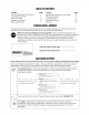
TABLE OF CONCH Content Page Content Page Important Safe Operation Practices 3 Maintaining And Servicing Your Edger a Assembling Your Edger 5 Off Season Storage 1" Know Your Edger 8 Trouble Shooting 1" Operating Your Edger 6 Illustrated Parts List 12 Making Adjustments 7 Warranty 16 0 DEL BE This Operator's Manual is an important part of your new edger. it will help you assemble, prepare and maintain the unit for best performance. Please read and understand what it says.
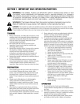
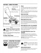
SECTION 1: IMPORTANT SAFE OPERATION PRACTICES WARNING: THIS SYMBOL POINTS OUT IMPORTANT SAFETY INSTRUCTIONS WHICH, IF NOT A FOLLOWED, COULD ENDANGER THE PERSONAL SAFETY AND/OR PROPERTY OF YOURSELF AND OTHERS. READ AND FOLLOW ALL INSTRUCTIONS IN THIS MANUAL BEFORE ATTEMPTING TO OPERATE THIS MACHINE. FAILURE TO COMPLY WITH THESE INSTRUCTIONS MAY RESULT IN PERSONAL INJURY. WHEN YOU SEE THIS SYMBOL — HEED ITS WARNING.
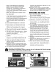
186. 17. 18. A Never operate with damaged safety devices. Failure to do so, can result in personal injury. Never run an engine indoors or in a poorly ventilated area. Engine exhaust contains carbon monoxide, an odorless and deadly gas. Do not aerate machine while under the influence of alcohol or drugs. Muffler and engine become hot and can cause a burn. Do not touch. Never operate this machine without good visibility or light. Always be sure of your footing and keep a firm hold on the handles.
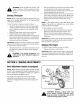
SECTION 2: ASSEMBLING YOUR EDGER IMPORTANT: This unit is shipped WITHOUT GASOLINE or OIL. After setting up the unit, service engine with gasoline and oil as instructed in the separate engine manual packed with your unit. NOTE: Reference to right or left hand side of the edger is observed from the operating position. Grounding the Engine’s Spark Plug + Disconnect the spark plug wire farm the spark plug and ground against the engine.
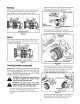
SECTION 3: KNOW THE EDGER Blade Control Bail Blade Depth “Control Lever {Transport Position Shown} Pull Rope / Recoil Starter Bevel Adjustment Lever(if Equipped] i Curb Height Adjustment Lever (f Equipped) Primer NOTE: Wheel and blade styles vary. Yours may differ slightly. Spindle Sheaves Belt Guard Figure 4 WARNING: Be familiar with all controls and their proper operation. Know how to stop the machine and disengage them quickly.
WARNING: Never fill fuel tank indoors, with A engine running or until the engine has been allowed to cool for at least two minutes after running. Starting The Engine NOTE: Refer to the Engine Manual packed with your edger for a detailed description of all engine-related controls and components. To start the edger’s engine, proceed as follows: + Attach the spark plug wire to the spark plug. Make certain the metal cap on the end of the spark plug wire is fastened securely over the metal tip on the spark plug.
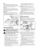
Beveling Set the bevel adjustment lever (refer to Figure 8) in the first (left hand) or third {right hand} notch to place the edger blade in position for beveling. See Figure 6. Beveling Positions Figure 6 Edging Set the bevel adjustment lever {refer to Figure 5} in the center notch to place the edger blade in a 80° position for edging. See Figure Edging/Trenching Position Figure 7 Trenching (models so equipped) NOTE: Edger features vary by model. All edger models do NOT come equipped for trenching.
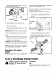
+ Secure with the bell washer and the hex lock nut governed earlier, See Figure 11, w_ \ fon} J Flat Washed Jf} A bp Triplex Blade Hex Lob Nut Figure 11 IMPORTANT: Use a torque wrench to tighten the hex look nut to between 37 fool-Abs. and 50 foot-BS. + Reinstall the spindle belt guard with the self tapping screws removed earlier. + Carefully place the drive belt back onto the engine flywheel pulley, and re tighten the flange lock nut on the top of the frame.
Wheels Lubricate the wheels and bearings at least once a season with a light oil. Also if the wheels are removed for any reason, lubricate the surface of the axle bolt and the inner surface of the wheel with light oll. Pivot Points Lubricate the pivot points on the blade control bail, blade depth control lever, and if applicable, the blade adjustment lever, and curb height adjustment lever with light oil at least once a season, Bearing Block The bearing block is equipped with a grease fitting.
+ Working from the front of the edger. place the belt ante the spindle sheaves, route it back onto the two idler pulleys, and then place it onto the engine flywheel pulley. IMPORTANT:Make certain that the *V” side of the belts seated into the top pulley and the flat side of the belt is seated into the bottom pulley. See Figure 15.
SECTION 9: MODEL 552 HANDLE 12 REF. PART REF. PART NO. NO. DESCRIPTION NO. NO.
Model 552 Frame REF, PART NO. NO. DESCRIPTION 1 710-0181 Screw, 2 710-0599 Screw, 3 710-0854A Screw, 4 710-0844 Screw, 5 712-0431 Flange Lock Nut, 6731-04168 Debris Guard 7 736-0320 Flat Washer, 3/810 x 1.37 OD B 736-0452 Belt Washer, 306 x 1.140 9 736-3082 Flat Washer, 406 x 1.00 10 736-3090 Flat Washer, 260 x.720 11750-04142 Pusey Mount Spacer 12 756-0313 Flat Idler Pulley, 1.
Model 552 Spindle Assembly V-BELTS are specially designed to engage and disengage safely. A substitute (non-UM) V-Belt can be dangerous by not disengaging completely. REF. PART REF. PART NO. NO. DESCRIPTION NO. NO. DESCRIPTION 1687-02019 Blade Plate Assembly 17 726-3090 Flat Washer, 2680 x.72 2 710-0385 Hex Screw, 516-18 18 737.
Model 552 Wheel Assembly {Frame shown for reference only) REF. PART NO, NO. DESCRIPTION 1887-02022 Curb Height Adjustment Lever 2 712-0431 Flange Lock Nut, 3732-04045 Torsion Spring 4 734-1284 Wheel 7x 1.75 5 734-1268 Wheel 8x 1.75 6 738-0182 Spring Washer, 500 x 1.00 7 736-0208 Flat Washer 51 1Dx 1.5 0D 8 736-0232 Wave Washer, 531 ID x.781 OD 9 736-0234 Washer, 385x 1.5 10 [736-0326 Flat Washer, 510x 1.00 11 738-0380 Shoulder Screw, 50 x 27 12738-04036 Shoulder Screw, 50 x 4.
MANUFACTURER'S LIMITED WARRANTY FOR: Yard-man) The limited warranty set forth below is given by MTD LLC with respect to new merchandise purchased and used in the United States, its possessions and territories. “MTD” warrants this product against defects in material and workmanship for a period of two (2) years commencing on the date of original purchase and will, at its option, repair or replace, free of charge. any part found to be defective in materials or workmanship.