Operator's Manual 21" Self-Propelled Mower Model 978Q IMPORTANT: Warning: Read safety rules and instructions carefully before operating equipment. This unit is equipped with an internal combustion engine and should not be used on or near any unimproved forest-covered, brush-covered or grass-covered land unless the engine's exhaust system is equipped with a spark arrester meeting applicable local or state laws (if any).
TABLEOFCONTENTS Content Page 3 6 7 9 10 Important Safe Operation Practices Slope Gauge Assembling Your Lawn Mower Know Your Lawn Mower Operating Your Lawn Mower Making Adjustments 11 Content Maintaining Your Lawn Mower Servicing Your Lawn Mower Off-Season Storage Troubleshooting Illustrated Parts List Page 13 14 16 17 18 Warranty 24 FINDINGMODELNUMBER This Operator's Manual is an important part of your new lawn mower. It will help you assemble, prepare and maintain the unit for best performance.
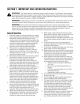
SECTION1: IMPORTANT SAFEOPERATION PRACTICES WARNING" This symbol points out important safety instructions which, if not followed, could endanger the personal safety and/or property of yourself and others. Read and follow all instructions in this manual before attempting to operate this machine. Failure to comply with these instructions may result in personal injury. When you see this symbol--HEED ITS WARNING.
immediately andthebladewillstoprotatingwithin 3. Do not mow on wet grass. Unstable footing could threeseconds. cause slipping. 9. Mowindaylightorgoodartificiallight;walk,notrun. 10.Stopthebladewhencrossinggraveldrives, Children walkwaysorroads. accidents can occur if the operator is not alert to 11.Iftheequipment shouldstarttovibrateabnormally, Tragic the presence of children. Children are often attracted to stoptheengineandcheckimmediately forthe the mower and the mowing activity. They do not cause.
10.Neveroverfillfueltank.Filltanktonomorethan½ inchbelowbottomoffillernecktoprovidespacefor fuelexpansion. 11.Replacegasolinecapandtightensecurely. 12.If gasolineisspilled,wipeitofftheengineand equipment. Moveunittoanotherarea.Wait5 minutesbeforestartingtheengine. 13.Neverstorethemachineorfuelcontainer inside wherethereisanopenflame,sparkor pilotlightas ona waterheater,spaceheater,furnace,clothes dryerorothergasappliances. 14.Toreducefirehazard,keepmowerfreeofgrass, leaves,orotherdebrisbuild-up.
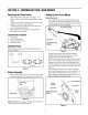
SIGHT AND HOLD THIS LEVEL WITH A VERTICAL TREE o E i,,II t- A POWER POLE I O A CORNER OF A BUILDING I OR A FENCE POST QI O cO r_ d) o *6 r- cO E o (D I rd) o 15 ° r,D o WARNING O3 64 cu o Do not mow on inclines with a slope in excess of 15 degrees (a rise of approximately 2-1/2 feet every 10 feet). A riding mower could overturn and cause serious injury.
SECTION3: ASSEMBLING YOURLAWNMOWER RemovingUnitFromCarton Setting UpYourLawn Mower • AssemblingHandle • • • Remove staples, break glue on top flaps, or cut tape at carton end and peel along top flap to open carton. Remove loose parts, if included with unit (i.e., grass bag etc.), and save it appropriately. Cut along corners, lay the carton down flat, and remove all packing material.
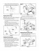
• Fasten the cable to the lower handle with the two cable ties found on the lower handle. Pull the cable ties tight and trim off the excess. See Figure 5. Bag Cable Tie Lower Handle Figure 5 Nuts Figure 7 Attaching StarterRope NOTE: Make certain the drive cable is routed around the outside and above the lower handle so it does not interfere with attaching the grass bag. • Lift chute door on the grass bag adapter and slide grass bag onto the adapter. See Figure 8.
SECTION4: KNOWYOURLAWNMOWER Read this operator's manual and safety rules before operating your lawn mower. Compare the illustration in Figure 10 with your lawn mower to familiarize yourself with the location of various controls and adjustments. Save this manual for future reference. ,_ mower can result WARNING" Theinoperation foreign objects of any being lawn thrown into the eyes, which can damage your eyes severely.
SECTION5: OPERATING YOURLAWNMOWER StartingEngine _ ARNING"andRead, understand, and follow all instructions warnings on the machine and in this manual before operating. ,_ NOTE: For shipping purposes your mower is set with the wheels in a low cutting height posfion. For best results, raise the cutting position until it is determined which height is best for your lawn. See the Adjustment Section for details. WARNING: Never run engine indoors or in enclosed, poorly ventilated areas.
StoppingEngine Mulching • Release blade control handle to stop the engine and the blade. • Disconnect spark plug wire and move away from spark plug to prevent accidental starting. For effective mulching, do not cut wet grass. New or thick grass may require a narrower cut. If the grass has grown in excess of 4", mulching is not recommended. Mow using the side discharge to reduce the grass height to 3.25" maximum before mulching.
To resolve the above problems, rotate the adjustment wheel with your fingers clockwise to tighten the cable and counter-clockwise to loosen the cable. See Figure 14. Bottom View HandleHeight Your mower is shipped with the handle in the higher height position. To lower the height, proceed as follows: • • Remove the starter rope from the rope guide. Remove the wing nuts and carriage bolts securing the upper handle. Remove and lay the upper handle out of the way, being careful not to bend or kink the cables.
SECTION7: MAINTAININGYOURLAWNMOWER ,i_ Inspect muffler periodically, and replace if necessary. Damaged mufflers or spark arresters can create a fire hazard. Make sure to avoid muffler WARNING" the Always stopwire the before engine and disconnect spark plug performing any maintenance work or adjustments on your lawn mower. and surrounding areas while the mower engine is hot because temperature of these areas of the engine may exceed 150 ° F.
SECTION8: SERVICING YOURLAWNMOWER • WARNING: Always stop the engine and disconnect the spark plug wire before performing any maintenance work or adjustments on your lawn mower. • • BladeCare WARNING: When removing the cutting blade for sharpening or replacement, protect your hands with a pair of heavy gloves or use a heavy rag to hold the blade. • • Periodically inspect the blade adapter for cracks, especially if you strike a foreign object. Replace when necessary.
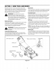
• Remove the three hex screws holding the baffle to the deck and pivot baffle towards the rear of the mower. See Figure 18. Squeeze the belt together and push it forward, while pressing the control arm inward towards the deck and remove the six speed cable from the slot. See Figure 21. Six-Speed Cable Slot Belt Control Arm Baffle Figure 18 Remove the hex bolt from the rear of unit holding the transmission to the mower housing. See Figure 19.
Pinch both sides of the belt together so that the belt is not in the pulley groove, and the lower pulley can be pushed towards the engine. See Figure 23. Lower Pulley Half_ • I o o Belt • • Make sure the belt is routed inside the pulley halves and the belt guard pin. Reinstall the bolt securing transmission to rear mower housing. Pivot the baffle back to its original position and secure with three hex screws removed earlier.
SECTION10: TROUBLESHOOTING Problem Cause Remedy Engine fails to start 1. 2. 3. 4. 5. 6. Blade control handle disengaged. Spark plug wire disconnected. Fuel tank empty or stale fuel. Blocked fuel line. Faulty spark plug. Engine flooded. 1. 2. 3. 4. 5. 6. Engage blade control handle. Connect wire to spark plug. Fill tank with clean, fresh gasoline. Clean fuel line. Clean, adjust gap, or replace. Wait a few minutes to restart, do not prime. Engine runs erratic 1. 2. Spark plug wire loose.
SECTION11: PARTSLISTFORMODEL978Q 17 2O 19 35 37 38 48 45 88 \ 28 57 27 .9 45 @ 91 31 73 72 76 3O 80 IMPORTANT: For a proper working machine, use Factory Approved Parts. V-BELTS are specially designed to engage 95-----_ and disengage safely. A substitute (non OEM) V-Belt can be dangerous by not disengaging completely.
Model978Q Ref. No. Part No. Ref. No. Description 1. 747-0824 Control Lever 52. 647-0004_ 731-0904A Deluxe Control Lever 2. Upper Control Housing 53. 3. 16864 4. 731-0620 6 Speed Rack Cable Bracket Drive Control Lever 5. 713-0397 6. 732-0627 7. Part No. Description 748-0381 Pawt RH 748-0188B Pawt LH 738-0137A Shld Screw.340 ID x.285 OD 54. 748-0318 Wheel Rachet 55. 736-0270 Bell Washer.265 ID x.75 OD Gear Insert 56. 710-0751 Hex Cap Screw 1/4-20 x.
Model978Q 26 15 16 _81 21 24 17 11 \ 4 5 25 \8 12 7 4 31 60 49 64 ]1 I 46\ 47_ 14 51 62 20
Model978Q Ref, No. Part No. Ref. No, Part Description Part No. Part Description 1. 720-0223 Grip 33. 712-0896 Hex Jam Nut 1/4-28 2. 732-0803A Spring Lever 34. 782-7598 Belt Keeper 3. 738-0529 Shoulder Nut.825 x.165 Lg. 35. 741-0124 Bearing 4. 5. 710-0751 736-0270 Cap Screw 1/4-20 x.620 Belt Washer.285 ID x.75 OD 36. 37. 732-0849A 750-1050 Extension Spring 6. 748-0318 Wheel Rachet 38. 682-0027A Idler Bracket Assembly 7. 736-0369 Flat Washer.508 ID x 1.00D 39.
Safety& DecorativeLabels 777S30116 (MODEL PLATE ON RIGHT SIDE) 777120291 777120067 777S30128 777S30145 TF/DO 22
NOTES 23
MANUFACTURER'S LIMITED WARRANTY FOR: YaRD.MaN TM ® The limited warranty set forth below is given by MTD LLC with respect to new merchandise purchased and used in the United States, its possessions and territories. "MTD" warrants this product against defects in material and workmanship for a period of two (2) years commencing on the date of original purchase and wilt, at its option, repair or replace, free of charge, any part found to be defective in materials or workmanship.