
Snow Thrower Operator's Manual

6
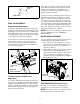
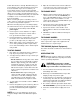
Figure 5
FINAL ADJUSTMENTS
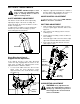
Auger Control Adjustment
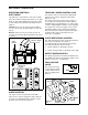
To check the adjustment of the auger control, push
forward on the left hand control, depressing the rub-
ber bumper on end of control. There should be slack
in the cable. Release the control. The cable should
be straight. Make certain you can depress the auger
control against the left handle completely.
If necessary, loosen the hex lock nut and thread the
cable in (for less slack) or out (for more slack) as
necessary. Recheck the adjustment. Tighten the
lock nut against the cable when correct adjustment
is reached. See Figure 6.
Figure 6
Traction Control and Shift Lever
Adjustment
To check the adjustment of the traction control and
shift lever, move the shift lever all the way forward to
sixth (6) position. With the traction control released,
push the snow thrower forward. The unit should roll
forward. Then engage the traction control grip. The
wheels should stop turning.
Now release the traction control, and push the unit
again. Move the shift lever back to the fast reverse
position, then all the way forward again. There
should be no resistance in the shift lever, and the
wheels should keep turning.
If you have resistance when moving the shift lever or
the wheels stop when they should not, loosen the
jam nut on the traction control cable and unthread
the cable one turn. If the wheels do not stop when
you engage the traction control grip, loosen the jam
nut on the traction control cable and thread the cable
in one turn. Recheck the adjustment and repeat as
necessary. Tighten the jam nut to secure the cable
when correct adjustment is reached.
NOTE: If you are uncertain that you have reached
the correct adjustment, refer to SECTION 6:
ADJUSTMENTS.
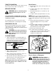
SKID SHOE ADJUSTMENT
The space between the shave plate and the ground
can be adjusted by adjusting the skid shoes.
1. Place skid shoes in the low position to remove
snow close to the ground. Place skid shoes in a
higher position to remove snow from uneven
ground. See Figure 7.
2. Adjust skid shoes by loosening the four hex nuts
and carriage bolts and moving skid shoes to
desired position. Make certain the entire bottom
surface of skid shoe is against the ground to
avoid uneven wear on the skid shoes. Retighten
nuts and bolts securely.
Figure 7
TIRE PRESSURE (Pneumatic Tires)
The tires are over-inflated for shipping purposes.
Check tire pressure and reduce to 15 to 20 psi.
NOTE: If the tire pressure is not equal in both tires,
the unit may pull to one side or the other.
Lamp Wire
Alternator
Lead
Right Handle
Hex Lock
Nut
Make Sure
Cable is Straight
Skid
Shoes
Carriage
Bolts
Hex Nuts