
Snow Thrower Operator's Manual


13
To remove shave plate, remove the carriage bolts,
bell washers and hex nuts which attach it to the snow
thrower housing. Reassemble new shave plate, mak-
ing sure heads of the carriage bolts are to the inside
of the housing. Tighten securely.
ENGINE
Refer to separate engine manual for all engine ser-
vice procedures.
BELT REMOVAL AND REPLACEMENT
WARNING: Disconnect the spark
plug wire from the spark plug and
ground.
AUGER BELTS
NOTE: It is necessary to remove both belts in
order to change either one. If changing just one belt,
be certain to check the condition of the other belt
model 600/610E has only one auger belt).
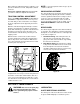
1. Remove the plastic belt cover on the front of the
engine by removing the two self-tapping screws.
See Figure 20.
2. Drain the gasoline from the snow thrower, or
place a piece of plastic under the gas cap.
3. Tip the snow thrower up and forward so that it
rests on the housing.
Figure 20
4. Remove six self-tapping screws from the frame
cover underneath the snow thrower.
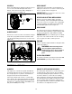
5. Roll the front and rear auger belts off the engine
pulley. See Figure 21.
Figure 21
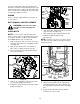
6. Unhook the idler spring from the hex bolt on the
auger housing. See Figure 22.
7. Back out the stop bolt to allow the belts to slip
between the bolt and auger pulley.
See Figure 23.
NOTE: It may be necessary to loosen the six hex
nuts that connect the frame to the auger housing to
aid in belt removal.
Figure 22
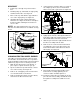
8. Lift the rear auger belt from the auger pulley,
and slip belt between the support bracket and
the auger pulley. Repeat this step for front auger
belt.
9. Replace both auger drive belts by following
instructions in reverse order.
Self-Tapping
Screws
Belt
Cover
Auger
Drive
Belt
Drive
Pulley
Idler
Pulley
Idler
Pulley
Auger
Drive
Drive
Belts
Pulley
Friction
Wheel
Support
Bracket
Auger
Pulley
Idler
Spring
Auger
Housing
Support
Bracket
Spring
Frame
Rear Auger
Belt
Front Auger
Pulley