O P E R AT I O N & M A I N T E N A N C E M A N U A L SERIE DIESEL ENGIEN O P E R AT I O N & M A I N T E N A N C E M A N U A L YANGDONG CO.
O P E R AT I O N & M A I N T E N A N C E M A N U A L Foreword Series Yangdong multi-cylinder diesel engines are ideal power units for light vehicle, agro motor, small tractor, air conditioner in bus, generator set and engineering machinery. The normal and reliable operation and long service life of the engine depend not only on the manufacturing quality, but also on the reasonable operation and correct maintenance.
O P E R AT I O N & M A I N T E N A N C E M A N U A L 10, ambient temperature under 0°C, discharge all the coolant to prevent frostbite after stop 11, all the filters(include air pump filter ) maitain,repair or instead according to the provision Notice of winter Make sure the usual running of engine; please pay attention the items as following: 1、please use “-10#”light diesel oil 2、please use Class CC or CD 10W/30 or 5w/30 diesel fuel, and the Class CD diesel fuel for turbine charger 3、Make sure the conne
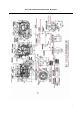
O P E R AT I O N & M A I N T E N A N C E M A N U A L Contents 1, Configuration and Installation dimension of model YSD490ZL (Fig.1) 2, Performance Curves of Model YSD490ZLD (Fig.2) Section 1. Diesel engine specification and technical dates 1、specification of diesel engine … ………………………………………………1-1 2、specification of the main accessories ………………………………………………1-4 3、Main technical data of diesel engines …………………………………………1-7 4、Fit clearance and wear limit of main parts … ………………………………………1-8 Section 2.
O P E R AT I O N & M A I N T E N A N C E M A N U A L 5、adjustment of injection pump …………………………………………………………………4-3 6、adjustment of decompression arm lash ……………………………… ……………………4-3 Section 5 Construction of diesel engine 1、cylinder head …………………………………………………………………5-1 2、cylinder block ………………………………………………………………………………5-2 3、piston 、connecting rod … 4、crankshaft and flywheel 5、camshaft …… …………………………………………………………………5-2 ……………………………………………………………………5-4 ……………………………………………………………………………………5-4 6、gear transmission system………
O P E R AT I O N & M A I N T E N A N C E M A N U A L 6
O P E R AT I O N & M A I N T E N A N C E M A N U A L 7
O P E R AT I O N & M A I N T E N A N C E M A N U A L 8
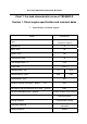
O P E R AT I O N & M A I N T E N A N C E M A N U A L Chart 7. the load characteristic curve of YSD490ZLD Section 1. Diesel engine specification and technical dates 1、specification of diesel engine Model Type YSD490ZLD line、water cool 、four stroke、direct combustion chamber Cylinder No. 4 Bore(mm) 90 Stroke(mm)` 100 Compression ratio 18 Total displacement(L) 2.54 Firing order Related power(kw) Related speed(r/min) 1-3-4-232 38.
O P E R AT I O N & M A I N T E N A N C E M A N U A L Net mass(kg) 280 Dimension (L×W×H)(mm) 733×628×610 2, specification of the main accessories Name No.
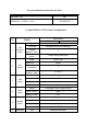
O P E R AT I O N & M A I N T E N A N C E M A N U A L 7 Fuel filter 8 Lube oil filter 9 Model JF13 或 JF15 Voltage (V) 14 Power (W) 350 或 500 Type Single stage, paper element Model C0506A Type Single stage, paper element Model J0708 或 J0810 或 J0810H Type Oil-immersed Model K1317A 或 CN212 Air filter 1-4 Name NO. Specification YD480 YSAD380 Series I or BQ pump Type 1 Fuel injection pump All-speed,mechnical centrifugal Governor Plunger 7.5 7.
O P E R AT I O N & M A I N T E N A N C E M A N U A L 7 Fuel filter 8 Lube oil filter 9 Air filter Model JF11 或 JFW13 或 JFW15 Voltage (V) 14 Power (W) 350 或 500 Type Single stage, paper element Model C0506A Type Single stage, paper element Model J0708 或 J0810 或 J0810H Type Oil-immersed Model Name NO.
O P E R AT I O N & M A I N T E N A N C E M A N U A L 7 Fuel filter 8 Lube oil filter 9 Air filter Voltage (V) 14 或 28 Power (W) 350 或 500 Type Single stage, paper element Model C0708B、CX0708B Type Single stage, paper element Model J0810、J0810H、J0814、JX0814 Type Oil-immersed Model KW1532、K1526 3, Main technical Data of diesel engines 1. Valve lash(mm) YSD490ZL intake valve(cold ) 0.30~0.35 exhaust valve(cold) 2. Sink age of valve 0.35~0.40 YSD490ZL sink age of valve 0.7~0.9 3.
O P E R AT I O N & M A I N T E N A N C E M A N U A L At normal operation 0.2~0.4 At min. steady speed ≥0.065 5. Governor characteristics Min .Idling steady speed (r/min) 6. Oil sump capacity ≤900 steady regulation(%)≤5 YSD490ZL oil sump capacity (L) About 7 7. Battery (engine not include) capacity (A) ≥150 4、Fit clearance and wear limit of main parts YSD490ZL N0. Name Assembly limit Wear limit 1 connecting rod journal and connecting rod 0.052~0.118 0.
O P E R AT I O N & M A I N T E N A N C E M A N U A L Section 2. Operation and security requirements of engine 1, Fuel, lube Oil and Cooling water 1. Fuel. Users can choose diesel adopted according to local ambient temperature. In China, we choose according to GB252 light diesel. In summer adopt No.”0” light diesel, in winter adopt No.”10” light diesel. The diesel must be a long time precipitation before inject into tank (not less than 48h). During refueling should us cloth filters.
O P E R AT I O N & M A I N T E N A N C E M A N U A L discharge bolts of the diesel filter and injection pump. Then press handle pump on the transmission oil pump until the air inside the oil loop is discharged completely. Then screw up the discharge bolt before loosening the high pressure oil pipe joint nut at the end of the oil injector. Rotate the rank to discharge the air inside the high pressure oil pipe.
O P E R AT I O N & M A I N T E N A N C E M A N U A L reach about 80°C. 2, Increase or decrease of the diesel engine load and rotation speed shall be carried out evenly and gradually. Under normal conditions, it is not allowed to add or remove the load suddenly. 3. During the operation time of the diesel engine, pay attention often to seek if the reading on the instruments on the instrument panel is normal. Pay attention to the exhausted gas color and the operation sound.
O P E R AT I O N & M A I N T E N A N C E M A N U A L regional operators must be installed guardrail to prevent people and goods sliding down. 4. The engine when is working, need to equipped with water temperature meter, oil pressure meter and instructions system. 5.
O P E R AT I O N & M A I N T E N A N C E M A N U A L 1、Check the oil level is under the gauge rated range. New machine or long time no used machine should stop after five~ten minute low speed running when gas. Then use gauge measure the oil level. 2、Check the water level of heat changer 3、Check the oil level on the oil pump of the governor whether if at rated level. 4 、Exclude the leakage situation of water, oil and gas on the diesel engine.
O P E R AT I O N & M A I N T E N A N C E M A N U A L electrolyzed liquid surface shall be 10-15mm higher than the electrode board, and supplement distilled water when the electrolyzed liquid is insufficient. 11, Components disassembled due to maintenance work shall be cleaned before re-assembly, and the installation position shall be guaranteed correctly. Then start the diesel engine and check its operation. Remove errors and abnormal phenomena found.
O P E R AT I O N & M A I N T E N A N C E M A N U A L 9, Check the joints of the electric circuits of the electric equipment are firm or not, and the lead contact is good or not. If there is burning mark found, clean it immediately. 10. After 1000 hours of working accumulatively, add the following work: (1) Generally inspect the parts of the diesel engine, and carry out necessary repair and adjustment.
O P E R AT I O N & M A I N T E N A N C E M A N U A L ring, cylinder cover and air valve sealed surface. 5, The mouths of air inlet and exhaust pipes(muffler) shall be blocked with wood lid or plastic cloth to avoid immunities enter. 6, Diesel engine shall be placed in dry and clean location with good ventilation. It shall be covered to avoid dust drop. It is prohibited to pile chemical products near the diesel engine. The aforesaid oil sealing method can be used to preserve the machine for 3 months.
O P E R AT I O N & M A I N T E N A N C E M A N U A L 2、adjustment of injection timing In order to obtain the most economic fuel consumption rate and good operation functions of the diesel engine, the advanced for oil supply shall be adjusted properly. The adjusted value of the advanced angle for oil supply must comply with the requirements of technical parameters of the diesel engine.
O P E R AT I O N & M A I N T E N A N C E M A N U A L abnormal or parts are damaged, the diesel engine might have errors during operations such as block smoke, power and rotation speed decreases, temperature discharge too high or impact on the cylinder, etc. The judgment on oil injector with errors can adopt stop-in-turn method, i.e. loosen the connection nuts between oil injector and high presser oil pipe one by one to stop oil injection, and meanwhile observe the color of smoke exhaust.
O P E R AT I O N & M A I N T E N A N C E M A N U A L and then clamp the needle valve with iron thread plier, and pull out lightly to avoid napping. When cleaning the needle valve parts, scratch with wooden piece with gasoline or diesel but metal piece is not allowed. When the needle valve and its parts are not smooth or the movement is inflexible, grind adjustment can be carried out. Use clean diesel when grinding.
O P E R AT I O N & M A I N T E N A N C E M A N U A L dividers respectively into the air inlet and exhaust valves of the first cylinder and the rocker, check and adjust the clearance between the air valves and keep the cool clearance between within regulated value. After that, according to the cylinder working order to half rotate the vcrand and adjust the clearance between the air valves.
O P E R AT I O N & M A I N T E N A N C E M A N U A L Section 5 Construction of diesel engine 1、cylinder head Fig.4 Tightening sequence of cylinder head bolts Fig.5 Valve sinkage The cylinder head is made of HT200 cast iron (with copper chrome). Fix it on the cylinder body with bolts for the cylinder head. When tightening the bolts for assembling, torsion spanner is employed to tighten as the figure 4 indicated below, then the required tightening force moment is achieved.
O P E R AT I O N & M A I N T E N A N C E M A N U A L required. As for a new one, sinking distance between the plane of the air inlet and air outlet and the plane of the cylinder head is 0.7-0.9mm, as figure 5 indicated. After amendment to it for many times, the sinking distance may be increased. When it exceeds 2mm, it’s recommended to change the valve seat. The valve clearance shall be checked regularly. See Section 1 of chapter V for detail on adjustment methods.
O P E R AT I O N & M A I N T E N A N C E M A N U A L dismantling it for cleaning, do not mistake the upper and low shaft bushings (the upper shaft bushing with oil groove). The thrust plate is locates at the last piece of the main bearing. Each of the two is located at the front and back end respectively. The thrust plate bears axial thrust of the crankshaft, with oil groove on the work surface and the reverse side. After crankshaft assembly is completed, it shall be flexible.
O P E R AT I O N & M A I N T E N A N C E M A N U A L abrasion, it still remains a certain of radial resilience, therefore, it extends service life of the oil control ring. Please check clearance of the opening before installing the piston. Keep the piston ring flat. 15-20mm away from top face of the cylinder sleeve. Then measure it gas feeler, clearance of the opening shall be 0.3-0.4mm. See figure 7 for detail.
O P E R AT I O N & M A I N T E N A N C E M A N U A L the cylinder sleeve carefully, and tighten the bolts in turn with required force moment. 4、crankshaft and flywheel Timing gear for the crankshaft and belt pulley are installed at the front of the crankshaft, The flying wheel is installed at the back flange and positioned by the positioning pin.
O P E R AT I O N & M A I N T E N A N C E M A N U A L The gear transmission system consists of timing gear for crankshaft, timing gear for cam shaft, timing gear for fuel injection pump and one inertia pump. Fig9: timing gear meshing signs Each timing gear is marked with timing gear except the gear for hydraulic pump.
O P E R AT I O N & M A I N T E N A N C E M A N U A L Figure 10 fuel adjustment diagrams 1. fuel return pipe 2. Fuel injection pipe 3. Injector 4. injection pump 5. Fuel filter 6. Governor 7. fuel delivery pump The fuel conveying pump takes charge of conveying the fuel to the diesel filter, then to the fuel blowout pump. The fuel generates high pressure in the fuel blowout pump, then spray into the combustion room to burn from fuel injector through high pressure duct in the form of mist.
O P E R AT I O N & M A I N T E N A N C E M A N U A L move the stopping working handle to realize emergency stop. Pin valve of the fuel injection nozzle and pin valve body are the precise couple parts by grinding, during dismantling, do not exchange it and keep it clean. 8、 Lubrication systems The lubrication system consists of the oil collecting and filter, oil pump, lubrication filter and kinds of the pipes, referring to Fig11. Diesel adopts pressure and splash lubricate.
O P E R AT I O N & M A I N T E N A N C E M A N U A L 9、cooling system Fig12 Cooling system 1 radiator pump 2 heat retainer 3 fan 4 water 5 inlet pipe The cooling system is of forcible circulating water-cooled type, see figure 12 for detail. The cooling system contains radiator, water pump, fan, heat retainer, air guide cover and etc.
O P E R AT I O N & M A I N T E N A N C E M A N U A L accelerate abrasion of the bearing. If some unusual noise be heard when bearing operates, it should be changed. As the “Technical Maintenance” required, the calcium-radical lubricant will be added to the Oil cup of the water pump regularly. The lubricant should not be added more than 1/2~1/3 of cavum of the bearing, otherwise will cause the bearing hotness.
O P E R AT I O N & M A I N T E N A N C E M A N U A L Charging generator adopt silicon commutate and shunt excitation JF21 model. It is comprised of three-phase A.C motor and silicon diode. The negative pole is grounded; otherwise, it may damage the generator. See operation and maintenance Manual for Silicon Commutate Generator of JF Series on operation and maintenance of the generator. Tooth of starting motor and flying wheel gear ring of diesel is controlled by electromagnetic switch.
O P E R AT I O N & M A I N T E N A N C E M A N U A L Section 6 Operation notice of turbo- charger diesel engine Turbocharger mounted at the exhaust pipe of the diesel engine. Exhaust gas discharged from the cylinder entry turbocharger casing through exhaust pipe drives impeller of the turbine, then drives impeller of the compressor push the pressed air filtered by air filtered into cylinder.
O P E R AT I O N & M A I N T E N A N C E M A N U A L coking of oil or blocking lubrication pipe, the responsibilities shall be borne by the customers. Selected oil brand under different temperatures Ambient temperature oil brand corresponding oil brand of SAE -10°C or colder 15W/40 CD grade 15W/40 CD grade -5°C~20°C 10W/30 CD grade 10W/30 CD grade 20°C or warmer 5W/30 CD grade 5W/30 CD grade The above-mentioned brand can be sold around China.
O P E R AT I O N & M A I N T E N A N C E M A N U A L the requirement of noise-damping, but also the resistance not exceed the permissible value(13~20kPa),power loss of the diesel not exceed than 3%~ 4%. 4 Fan of diameter 420mm is a standby accessories for turbcharging diesel. We recommend to use the fan whose a diameter no less than 420mm when change it. Heat radiation area: heat radiation area for YSD490ZL turbo charging diesel according to the power.
O P E R AT I O N & M A I N T E N A N C E M A N U A L of the push rod and turbocharger can not work normally. Attention: the diesel can not work under the conditions of no air filter providing or available, and leakage of the air inlet and outlet system. 9 Prohibit operations under long-term overload condition. The diesel work overload for a long time, the speed of engine will be slow, cause low speed of the turbocharger, departure high effective area.
O P E R AT I O N & M A I N T E N A N C E M A N U A L When the diesel is heated, do not touch the turbo charging and its connections to avoid scalding.
O P E R AT I O N & M A I N T E N A N C E M A N U A L 7、battery lose electricity Charge the battery 8 、 wires connections check and tighten wire connections, clean contact points loosened 9 ambient tem.
O P E R AT I O N & M A I N T E N A N C E M A N U A L 2 spray instruction ill check the spray atomization, fuel pressure and if the pump is damaged, replace it 3 inferior quality of fuel Use eligible fuel 4 combustion incomplete Main reason is :fuel pump atomizes bad, delivery fuel advanced angle incorrect, leakage at cylinder cover gaskets and low compression pressure.
O P E R AT I O N & M A I N T E N A N C E M A N U A L 5、 lube oil insufficiency or no pressure 1 oil lever in oil sump too low 2 serious leakage from oil pipelines 3 extract oil filter, oil filter and pipe blocked 4 oil gauges damaged or gauge pipe blocked 5 oil is too dilute 6 oil pump gears seriously worn off, with excessive clearance 7 pressure relief valves of oil filter cease to function 8 main bearings connecting-rod bearings and camshaft bushing seriously worn off with excessive clearance Add oil up
O P E R AT I O N & M A I N T E N A N C E M A N U A L (2)oil pressure too low with insufficient (2)refer to paragraph V.
O P E R AT I O N & M A I N T E N A N C E M A N U A L turbocharger and the diesel engine. If believing the trouble caused by turbocharger doesn’t unload the turbocharger from the diesel immediately, especially neither disassembles it. Eliminating the fault by replacing the turbocharger simply can’t solve the problem, but also causes the new problem. Should diagnose the fault, and eliminate it after finding out the problem.
O P E R AT I O N & M A I N T E N A N C E M A N U A L √ √ √ √ √ √ √ √ √ √ √ √ √ √ √ √ √ √ √ √ √ √ √ √ √ between air filter and compressor replace the sealing element The pipe between the compressor and the intake pipe leakage Tighten fastener or replace sealing element The contacting face of the intake manifold branch the cylinder head of the diesel engine leak-off replace gasket or tighten fastener Compressor’ s intake pipe blockage Eliminate impurity or replace damaged part
O P E R AT I O N & M A I N T E N A N C E M A N U A L √ √ √ √ √ √ √ √ √ √ √ √ √ √ √ √ √ √ element Engine’s outlet pipe blockage Eliminate impurity Turbine combustion outtake leak gas √ √ cylinder head √ √ Muffler or exhaust tail pipe blockage Tighten fastener or replace sealing element Eliminate impurity or change √ Supercharge r’s oil return pipe blockage √ Crankcase’s breathing apparatus blockage Eliminate impurity or replace √ Supercharge r’s middle case dirty or baking
O P E R AT I O N & M A I N T E N A N C E M A N U A L Compressor’ s impeller wear out or damage Clean air intake system or replace supercharg er √ Supercharge r’s bearing, bearing bore or shaft diameter wear out Replace supercharg er √ Improper lube oil Choose specified lube oil √ √ Appendix: No. 1 2 3 4 5 6 7 8 9 wearing parts order sheet Name Cylinder sleeve Piston ring Piston Oil seal Charger Start motor Air gate Valve retainer Valve guide No.
O P E R AT I O N & M A I N T E N A N C E M A N U A L maintenance. Please operate and maintenance according to our manual to prolong wearing part’s life, otherwise the life will be shortened seriously. Production permit No.:XK06-205-00141/XK06-00141 Product standard:Q/321284 JCA03-2002;Q/321284 JCA06-2002 address; website: email: phone: fax: post code No.230LuotangEastRoad.Jiiangyan City Jiangsu province China www.yangdong.com yangdong@yangdong.