Programmable Low Temperature Incubator Model IN603/803 Instruction Manual - Second Edition - z Thank you for purchasing " Programmable Low Temperature Incubator, IN Series" of Yamato Scientific Co., Ltd. z To use this unit properly, read this "Instruction Manual" thoroughly before using this unit. Keep this instruction manual around this unit for referring at anytime. WARNING!: Carefully read and thoroughly understand the important warning items described in this manual before using this unit.
Contents Cautions in Using with Safety................................................................ 1 • • • Before Using this unit ............................................................................. 4 • • • Requirements for Installation......................................................................................... 4 When Using the Unit ..................................................................................................... 7 Defrost in Refrigerator ............
Handling Precautions ........................................................................... 52 Maintenance Method............................................................................. 53 • Long storage and disposal................................................................... 54 • Daily Inspection and Maintenance .............................................................................. 53 When not using this unit for long term / When disposing ...........................
Cautions in Using with Safety Explanation MEANING OF ILLUSTRATED SYMBOLS Illustrated Symbols Various symbols are used in this safety manual in order to use the unit without danger of injury and damage of the unit. A list of problems caused by ignoring the warnings and improper handling is divided as shown below.Be sure that you understand the warnings and cautions in this manual before operating the unit.
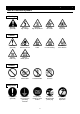
Cautions in Using with Safety Table of Illustrated Symbols Warning Warning, generally Warning, high voltage Warning, high temperature Warning, drive train Warning, explosive Caution, generally Caution, electrical shock Caution, scald Caution, no road heating Caution, not to drench Caution, water only Caution, deadly poison Prohibit, inflammable Prohibit, to disassemble Prohibit, to touch Compulsion, connect to the grounding terminal Compulsion, install on a flat surface Compulsion, discon
Cautions in Using with Safety Fundamental Matters of "WARNING!" and "CAUTION!" WARNING! Do not use this unit in an area where there is flammable or explosive gas Never use this unit in an area where there is flammable or explosive gas. This unit is not explosion-proof. An arc may be generated when the power switch is turned on or off, and fire/explosion may result. (Refer to page 63 "List of Dangerous Substances".
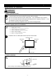
Before Using this unit Requirements for Installation WARNING! 1. Always ground this unit • Be sure to connect the earth wire (the green cable of power cord) to the grounding conductor or ground terminal to prevent accidents caused by electric leakage. • Do not connect the earth wire to gas or water pipes. If not, fire disaster may be caused. • Do not connect the earth wire to the ground for telephone wire or lightning conductor. If not, fire disaster or electric shock may be caused.
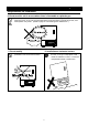
Before Using this unit Requirements for Installation 4. Do not use this unit in an area where there is flammable or explosive gas • Never use this unit in an area where there is flammable or explosive gas. This unit is not explosion-proof. An arc may be generated when the power switch is turned ON or OFF, and fire/explosion may result. (Refer to page 63 "List of Dangerous Substances".) 改造 5. Do not modify 6. Installation on horizontal surface • Set this unit to the flattest place.
Before Using this unit Requirements for Installation 7. Choose a correct power distribution board or receptacle • Choose a correct power distribution board or receptacle that meets the unit’s rated electric capacity. Electric capacity: IN603: 100V AC 10A, IN803: 100V AC 12A NOTE) Starburst connection with a branching receptacle or extended wiring with a cord reel lowers electrical power voltage, which may cause the degradation of the refrigeration capability or temperature control performance. 8.
Before Using this unit When Using the Unit CAUTION! 1. Do not use explosive or flammable substance • Never use explosive substances, flammable substances and substances that include explosive or flammable ingredients in this unit. Explosion or fire may occur. Flammable or explosive substance 2. Do not make an overload 3. Do not set samples in close formation • The temperature in furnace cannot be controlled if too much samples are set there.
Before Using this unit Defrost in Refrigerator Much frost on the evaporator degrades the refrigeration capability, which may cause uncontrollability of setting temperature. In the IN602 or IN802, the condition of frost on the evaporator can be checked through the frost inspection window inside furnace. The frosting speed varies depending on the following conditions.
Description and Function of Each Part Main Unit IN603 Front view Production plate Shelf Shelf bracket Inner door Magnetic packing Cable port Specification plate Independent overheating prevention device Power plug Control panel Power switch (Earth leakage breaker) Rear view Power cord 9
Description and Function of Each Part Main Unit IN803 Independent overheating prevention device Front view Control panel Power switch (Earth leakage breaker) Shelf bracket Production plate Magnetic packing Cable port Inner door Specification plate Shelf Power plug Rear view Power cord 10
Description and Function of Each Part Structure Chart IN603 棚板 Shelf Door扉パッキン packing ファン Fan Inner内扉 door Temperature 温 度 sensor センサ Heater ヒータ Evaporator 蒸発器 Frost checking 霜観測窓 window Condenser コンデンサ Control panel コントローラ操作パネル Compressor コンプレッサ 11
Description and Function of Each Part Structure Chart IN803 棚板Shelf コントローラ Control panel 操作パネル Door packing 扉パッキン ファン Fan 温度センサ sensor Temperature (Pt&K double ダブルセンサ) (Pt&K sensor) Inner 内扉door Heater ヒータ Frost checking 霜観測窓 window Evaporator 蒸発器 コンデンサ Condenser Compressor コンプレッサ 12
Description and Function of Each Part Control Panel 5 6 7 8 3 2 1 4 FIXED TEMP AUTO STOP AUTO START ℃ PROGRAM 9 10 11 12 DEFROST TROUBLE STANDBY END HEATER REFRIGE FUNCTION PROGRAM MENU 13 14 15 16 ENTER CANCEL 18 19 17 POWER 20 1 Main Display: Displays the measured temperature and error code. 2 Sub Display: Displays the operation and setting information. 3 TROUBLE Lamp: Blinks when a trouble occurs. 4 DEFROST key: Starts/stops the defrost operation.
Operation Method Key Operation Chart of Mode Setting and Program Registering 14
Operation Method Operation Mode and Function List The operation mode consists of the following four modes. No. Name Description Page 1. Fixed Temperature Operation Controls temperature with fixed temperature. 16 2. Auto Stop Operation Stops operation at specified time. 19 3. Auto Start Operation Starts operation at specified time. 22 4. Program Operation Starts program operation at specified time. 24 The function menus are listed below.
Operation Method Fixed Temperature Operation Start the operation from turning on the power shown in the figure, and continue the operation under the setting temperature unless turning off the power. SV SV: Setting temperature t: Time t ▲ STOP ▲ START Setting of the Fixed Temperature Operation 1 Turn on the power • Turn on the power switch of the unit (earth leakage breaker). Pressing the POWER key turns on the power. The Main Display indicates the temperature in furnace.
Operation Method Fixed Temperature Operation 3 Set temperature FIXED TEMP Set TEMP AUTO STOP AUTO START ℃ PROGRAM STANDBY END HEATER REFRIGE FUNCTION PROGRAM 0.0℃ Fixed TEMP OPR MENU ENTER DEFROST TROUBLE CANCEL POWER FIXED TEMP Set TEMP ℃ PROGRAM 37.0℃ Fixed TEMP OPR DEFROST FUNCTION PROGRAM MENU ENTER CANCEL POWER Start operation FIXED TEMP Set TEMP AUTO STOP AUTO START ℃ PROGRAM 37.
Operation Method Fixed Temperature Operation 5 Vary the temperature FIXED TEMP Set TEMP AUTO STOP AUTO START ℃ PROGRAM STANDBY END HEATER REFRIGE FUNCTION PROGRAM 37.0℃ Fixed TEMP OPR MENU ENTER DEFROST ① Make the setting temperature blinking using the " ▲▼" during the fixed temperature operation. TROUBLE CANCEL POWER ② Vary the temperature using the "▲▼". FIXED TEMP Set TEMP AUTO STOP AUTO START ℃ PROGRAM 30.
Operation Method Auto Stop Operation As shown in the following figure, the device stops operating automatically by setting the timer. Set timer ▼ SV SV: Setting temperature t: Time Waiting Start operation (manual) t Operation period Activate timer Stop operation (auto) Setting of the Auto Stop Operation 1 Turn on the power • Turn on the power switch of the unit (earth leakage breaker). Pressing the POWER key turns on the power. The Main Display indicates the temperature in furnace.
Operation Method Auto Stop Operation 3 Set temperature and operation period/stop time. FIXED TEMP Set TEMP AUTO STOP AUTO START ℃ PROGRAM 0.0℃ Auto-stop OPR DEFROST TROUBLE STANDBY END HEATER REFRIGE FUNCTION PROGRAM MENU ENTER CANCEL POWER ① The setting temperature input screen is displayed. The Sub Display indicates "Set TEMP" and the numeric character that indicates temperature blinks. ② Set the temperature using the "▲▼".
Operation Method Auto Stop Operation 4 Start operation FIXED TEMP Set TEMP AUTO STOP AUTO START ℃ PROGRAM STANDBY END HEATER REFRIGE FUNCTION PROGRAM 37.0℃↑ Stop in MENU 30min ENTER DEFROST TROUBLE CANCEL POWER ① Press the ENTER key to decide the setting and the auto stop operation starts. The blinking AUTO STOP lamp lights on and the Sub Display displays the setting temperature and residual time to operation stop.
Operation Method Auto Start Operation As shown in the following figure, this mode is applied to the device for starting the operation after the specified time (hours) automatically. Note that the device does not stop the operation automatically. Stop the operation by manual without fail.
Operation Method Auto Start Operation 3 Set temperature and start wait period/time FIXED TEMP Set TEMP AUTO STOP AUTO START ℃ PROGRAM STANDBY END HEATER REFRIGE FUNCTION PROGRAM 0.0℃ Auto-start OPR MENU DEFROST TROUBLE ENTER CANCEL POWER ② Set the temperature using the "▲▼". FIXED TEMP Set TEMP AUTO STOP AUTO START ℃ PROGRAM ③ Press the ENTER key to decide the temperature. 37.
Operation Method Program Operation As shown in the figure, this mode is used for running the device under the setting program. Start pv (Temperature) Setting temperature Step1 Step2 Step3 Step4 Start program Step5 Step6 Step7 Step8 (Time) End program Setting of the Program Operation 1 Turn on the power • Turn on the power switch of the unit (earth leakage breaker). Pressing the POWER key turns on the power. The Main Display indicates the temperature in furnace.
Operation Method Program Operation 3 Set step number and start wait period/ time FIXED TEMP First step AUTO STOP AUTO START ℃ PROGRAM S01 Program OPR DEFROST TROUBLE STANDBY END HEATER REFRIGE FUNCTION PROGRAM MENU ENTER CANCEL POWER ① The initiating step input screen is displayed. The Sub Display displays "First step" and the step number blinks. ② Select the step number using the"▼▲" and then check it using the ENTER key.
Operation Method Program Operation 4 Start operation FIXED TEMP Step AUTO STOP AUTO START ℃ PROGRAM S01 Start in DEFROST 30min TROUBLE STANDBY END HEATER REFRIGE FUNCTION PROGRAM MENU FIXED TEMP ENTER Set TEMP AUTO STOP AUTO START ℃ PROGRAM CANCEL 37.0℃↑ Step S01 POWER DEFROST TROUBLE STANDBY END HEATER REFRIGE FUNCTION PROGRAM MENU ENTER CANCEL POWER ① Press the ENTER key to decide the operation start wait period/time. The unit enters to program operation wait state.
Operation Method Input Program 1 Select program function • Check that the power in turned on. PROGRAM Select step S01 Program OPR TROUBLE ENTER 2 CANCEL ① Press the PROGRAM key. The program menu starts and step number selection screen is displayed. Press the "▼▲". The registered step numbers and the smallest number of un-used step are displayed in sequence. Select the step number among them. The "S01" is displayed when no program is registered. In this case, the "▼▲" are invalid.
Operation Method Input Program 2 • The temperature is kept constant till the end of setting time when the "START TEMP" and the "Set Temp" are the same. The unit enters into "Wait" and measurement of residual time is suspended when the temperature in furnace is within ±1℃ to the setting temperature. TEMP. START. TEMP. Set Temp. TIME Set Time • The unit operates with full-power from the "START TEMP" to the "Set Temp" when the period is set to 0 minute.
Operation Method Input Program 2 ① After the step number is decided, the setting item selection screen is displayed. items on the Sub Display using the PROGRAM key. No. Item 1 Setting temperature 2 Setting time 3 Repeat initiating step 4 Repeat count 5 Step insertion 6 Step deletion 7 Program end Sub Display Set TEMP Select the Notes 37.0℃ S01 Set time 0min S01 Rep. start S01 S01 Rep. count 5 S01 Insert step Add a new step at the position of step currently referred to.
Operation Method Input Program 2 ② Select the "Set TEMP" and press the ENTER key. The temperature setting edition screen is displayed. The blinking "" (cursor) goes out and the setting value blinks instead. Set TEMP ENTER Set TEMP ► 30.0℃ → S01 S01 (Selection screen) (Edition screen) ③ Select the temperature using "▼▲" and press the ENTER key. screen returns to the setting item selection screen. Set TEMP 37.
Operation Method Input Program 3 Insert step into the position currently displayed ① Display the "Insert step" on the setting item selection screen and then press the ENTER key. The screen returns to the setting item selection screen and the setting temperature of inserted step is displayed. The "Insert step" is not displayed if no steps are left. Insert step Set TEMP S01 S01 TROUBLE ENTER 0.
Operation Method Input Program 5 Delete step currently displayed • Check that any program is registered. ① Select the "Delete step" and press the ENTER key. Delete step S01 TROUBLE ENTER CANCEL Pressing the "CANCEL key before pressing the ENTER quit the deletion. 6 End program edition ① Select the "Program End" on the setting item selection screen and press the ENTER key. edited program is saved and the edition is completed.
Operation Method Program Creation Example • The program pattern below is explained as an example. 1 Step No. Setting Temp. Setting Time Repeat Start Repeat Count S01 50.0℃ 30min No - S02 20.0℃ 0min No - S03 ℃-10.0 15min S02 1 S04 - End - - Press the PROGRAM key to display the step number selection screen. Select step S01 Program OPR TROUBLE ENTER 2 Display "SO1" using the "▼▲". CANCEL Select step S01 Program OPR 3 Press the ENTER key to display the "Set TEMP".
Operation Method Program Creation Example 11 Press the PROGRAM key to display the "Rep. start". Rep. start ► No S01 12 Press the ENTER key to display the repeat initiating step edition screen. The cursor goes out and the setting for repeat initiating step blinks. 13 Set the "No" using the "▼▲". Rep. start No S01 Rep. start ► No S01 14 Press the ENTER key to decide the setting. Rep. start ► No S01 15 Press the PROGRAM key until the "Set TEMP" in the Step 2 is displayed.
Operation Method Program Creation Example 25 Set the "No" using the "▼▲". Rep. start ► No S02 26 Press the ENTER key to decide the setting. Rep. start ► No S02 27 Press the PROGRAM key until the "Set TEMP" in the Step 3 is displayed. The display on the lower column changes from "S02" to "S03"or to "SO3 (un-used)". 28 Press the ENTER key to display the setting temperature edition screen. The cursor goes out and the setting temperature blinks. 29 Set the temperature to -10℃ using the "▼▲".
Operation Method Program Creation Example 39 Press the PROGRAM key to display the "Rep. count". Rep.count ►Endless S03 40 Press the ENTER key to display the setting for repeat count edition screen. The cursor goes out and the repeat count blinks. 41 Set "1" using the "▼▲". Rep. count Endless S03 Rep. count 1 S03 42 Press the ENTER key to decide the setting. Rep.count ► 1 S03 43 Press the PROGRAM key until the "Set time" in the Step 4 is displayed.
Operation Method Set Clock The clock is not set at factory shipment. Set it with your watch or time tone before using the unit. The setting for clock can not be changed at the operation start waiting state in the auto start mode/program mode, or during operation. Press the POWER key and stop operation to change it. 1 Select the item in function menu • Check that the power in turned on. ① Press the FUNCTION key. The function menu starts and the Sub Display displays the items.
Operation Method Set Clock 3 4 Input value Date 2001/09/22 Time 17:30 Date ↓ 2002/09/22 Time 17:30 ① The "" (cursor) goes out and the current value blinks instead. Display the desired value using the "▼▲". Set clock Date 2002/09/22 Time 23:59 ENTER ① Press the ENTER key. The setting is decided and the function menu selection screen is displayed.
Operation Method Set the Timer Mode Changes in timer mode are not reflected in the operation currently carried out in the following state of unit; operation start waiting state in the auto start mode, during auto stop mode operation, and operation start waiting state in the program operation mode. The changes are reflected on and after the next operation. 1 Select the item in function menu • Check that the power in turned on. ① Press the FUNCTION key.
Operation Method Set the Operation Start Signal Input Mode 1 Select the item in function menu • Check that the power in turned on. ① Press the FUNCTION key. The function menu starts and the Sub Display displays the items. Select the item using the FUNCTION key. FUNCTION OPR signal ② Display the "OPR signal" and press the ENTER key. Press the CANCEL key to cancel the function menu.
Operation Method Set the Operation Stop Signal Input Mode 1 Select the item in function menu • Check that the power in turned on. ① Press the FUNCTION key. The function menu starts and the Sub Display displays the items. Select the item using the FUNCTION key. FUNCTION Stop signal ② Display the "Stop signal" and press the ENTER key. Press the CANCEL key to cancel the function menu.
Operation Method Set the Key Lock Mode 1 Select the item in function menu • Check that the power in turned on. ① Press the FUNCTION key. The function menu starts and the Sub Display displays the items. Select the item using the FUNCTION key. FUNCTION Key lock ② Display the "Key lock" and press the ENTER key. Press the CANCEL key to cancel the function menu. OFF TROUBLE ENTER 2 CANCEL Select mode Key lock OFF ① The "" (cursor) goes out and the mode currently selected blinks instead.
Operation Method Set the Buzzer Mode 1 Select the item in function menu • Check that the power in turned on. ① Press the FUNCTION key. The function menu starts and the Sub Display displays the items. Select the item using the FUNCTION key. FUNCTION Buzzer mode ② Display the "Buzzer mode" and press the ENTER key. Press the CANCEL key to cancel the function menu.
Operation Method Calibration Offset Function Calibration offset is a function which corrects the difference between the temperature in furnace and that of controller (sensor temperature) if arises. The function parallel corrects the difference either to the plus or minus side within the whole temperature range of unit.
Operation Method Calibration Offset Function 3 Set calibration offset Calibrate +2.5℃ TROUBLE ENTER CANCEL (Ex.) Indicated temperature on controller: 37℃ Measured temperature: 36℃ ↓ Calibration offset: -1 ① Press the ENTER key. The setting is decided and the function menu selection screen is displayed. Offset is adjustable within the range from +3.0℃ to -3.0℃.
Operation Method Integrating Operation Time The integrating operation time is a function to check the operation hours of unit. Its content can not be changed. 1 Select the item in function menu • Check that the power in turned on. ① Press the FUNCTION key. The function menu starts and the Sub Display displays the items. Select the item using the FUNCTION key. FUNCTION 2 Check integrating operation time Acc.
Operation Method Set the Defrost Operation Mode 1 Select the item in function menu • Check that the power in turned on. ① Press the FUNCTION key. The function menu starts and the Sub Display displays the items. Select the item using the FUNCTION key. FUNCTION DEF mode ② Display the "DEF mode" and press the ENTER key. Press the CANCEL key to cancel the function menu. OFF TROUBLE ENTER 2 CANCEL Select mode DEF mode OFF ① The "" (cursor) goes out and the mode currently selected blinks instead.
Operation Method Set the Cycle Defrost Operation Time 1 Select the item in function menu • Check that the power in turned on. ① Press the FUNCTION key. The function menu starts and the Sub Display displays the items. Select the item using the FUNCTION key. FUNCTION Cycle ►5min ON DEF 2 23h55m OFF ② Display the "Cycle/DEF" using the FUNCTION key. • The Sub Display displays the current setting of cycle defrost operation time for "ON" and "OFF". Press the CANCEL key to cancel the function menu.
Operation Method Set the Refrigerator Operation Mode 1 Select the item in function menu • Check that the power in turned on. ① Press the FUNCTION key. The function menu starts and the Sub Display displays the items. Select the item using the FUNCTION key. FUNCTION REF mode ② Display the "REF mode" and press the ENTER key. Press the CANCEL key to cancel the function menu.
Operation Method Set the Communication Lockout Mode (Optional accessory) 1 Select the item in function menu • Check that the power in turned on. ① Press the FUNCTION key. The function menu starts and the Sub Display displays the items. Select the item using the FUNCTION key. FUNCTION Comm. Lockout ② Display the "Comm. Lockout" and press the ENTER key. OFF TROUBLE ENTER 2 3 CANCEL Select mode Comm. Lockout OFF ↓ Comm.
Operation Method The Independent Overheating Prevention Device 1 Select the item in function menu ① Set the temperature using the "▼▲". 60℃ Notes for the independent overheating prevention device • In case there is a small difference between the set values of temperature for the independent overheating prevention device and that of controller, the independent overheating prevention device may be activated and stops the operation.
Handling Precautions WARNING! If a problem occurs If smoke or strange odor should come out of this unit for some reason, turn off the power key right away, and then turn off the circuit breaker and the main power. Immediately contact a service technician for inspection. If this procedure is not followed, fire or electrical shock may result. Never perform repair work yourself, since it is dangerous and not recommended.
Maintenance Method Daily Inspection and Maintenance WARNING! • Disconnect the power cable from the power source when doing an inspection or maintenance unless needed. • Perform the daily inspection and maintenance after returning the temperature of this unit to the normal one. • Do not disassemble this unit. CAUTION! • Use a well-drained soft cloth to wipe dirt on this unit. Do not use benzene, thinner or cleanser for wiping. Do not scrub this unit.
Long storage and disposal When not using this unit for long term / When disposing CAUTION! When not using this unit for long term… • Turn off the power and disconnect the power cord. WARNING! When disposing… • Keep out of reach of children. • Remove the door and driving parts. • Treat as large trash. Environmental protection should be considered We request you to disassemble this unit as possible and recycle the reusable parts considering to the environmental protection.
In the Event of Failure… Error Indication Error code Name Cause Solution Er.00 Setting value error Setting value is out of usable range Set correct value. Er.01 Sensor error Temperature sensor failure Contact to our service division. Er.02 SSR error SSR failure Contact to our service division. Er.03 Heater error Heater disconnection (Detection is available only during Contact to our service division. the heater is controlled.) Er.
In the Event of Failure… Trouble Shooting Problem The device does not start when turning on the power switch. Temperature does not rise. Temperature does not fall. Heater does not stop working when the temperature reaches setting value. Possible Cause Solution Earth leakage breaker failure Replace the part. Power switch failure Replace the part. Power source failure Connect to the appropriate power source Heater disconnection Replace the part. SSR failure Replace the part.
After Service and Warranty In Case of Request for Repair If the failure occurs, stop the operation, turn OFF the power switch, and unplug the power plug. Please contact the sales agency that this unit was purchased, or the Yamato Scientific's sales office. < Check following items before contact > ◆ ◆ ◆ ◆ Model Name of Product See the production plate attached to this unit.
Specification IN603 IN803 Method Temperature control range Temperature adjustment accuracy Temperature distribution accuracy Time required to reach highest temperature Time required to reach lowest temperature Temperature control system Temperature setting system Temperature display system Timer display range Timer resolution Operation mode Additional functions Refrigerator Cooling medium Heater Heater circuit Fan of blower Sensor Interior Exterior Heat insulation material Inner door Safety device Defros
Specification IN603 IN803 Internal dimensions (W×D×H mm) 600×477×500 600×477×1000 External dimensions (W×D×H mm) 710×645×915 710×645×1630 150L 300L Capacity Withstand load of shelf Number of shelf bracket step Interval of shelf bracket steps Power supply (50/60Hz) Weight Accessories Optional accessory 15kg/one shelf 13 23 30mm 100V AC, 10A 100V AC, 12A Approx. 90Kg Approx.
Wiring Diagram J1 J1 IN603 Symbol Part name Symbol Part name ELB Earth leakage breaker TH Temperature sensor 1, 2 Terminal block OH Independent overheating prevention device H1 Heater (internal) H2 Heater (door) SSR1, 2 Solid-state relay PLB PLANAR board PIO Display circuit board FM1 Fan motor (internal) FM3 Fan motor (refrigerator) CT1, 2 MV1 Solenoid valve (defrost) OVR MV1 Solenoid valve (returning tube) C1 Operation condenser Relay (internal heater) C2 Starting co
Wiring Diagram J1 J1 IN803 Symbol Part name ELB Earth leakage breaker 1, 2 Terminal block H1 Heater (internal) H2 Symbol Part name TH Temperature sensor OH Independent overheating prevention device SSR1, 2 Solid-state relay Heater (door) PLB PLANAR board Fan motor (internal) PIO Display circuit board Fan motor (refrigerator) CT1, 2 Current transformer MV1 Solenoid valve (defrost) OVR MV1 Solenoid valve (returning tube) C1 X1 Relay (internal heater) C2 Starting condense
Replacement Parts Table Common parts Part Name Control board (CR3R) Display circuit board Relay Relay Terminal block Terminal block Fan SSR Code No.
Reference List of Dangerous Substances Never use explosive substances, flammable substances and substances that include explosive or flammable ingredients in this unit.
Responsibility Please follow the instructions in this document when using this unit. Yamato Scientific has no responsibility for the accidents or breakdown of device if it is used with a failure to comply. Never conduct what this document forbids. Unexpected accidents or breakdown may result in. Note ◆ The contents of this document may be changed in future without notice. ◆ Any books with missing pages or disorderly binding may be replaced.