Instruction Manual for Incubator Shaker model IK 400 IK 400W IM 400 IM 400W 2nd Edition z Thank you for purchasing the Yamato Scientific IK/IM incubator shaker. z For correct use of the incubator shaker, read this manual and the guarantee thoroughly before use. After reading, keep the manual and the guarantee in a safe place for quick reference whenever required.
Index Symbol Conventions................................ ................................................................ ................................................................................................ ................................................................................................ ...................................................................... ...................................... 1 Safety precautions ................................................................
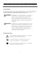
Symbol Conventions Safety Symbols The following safety symbols are used on the product and in this manual. Be sure to follow the instructions and requirements on safety described in this manual when handling the product. Yamato Scientific Co., Ltd. assumes no liability for failure to comply with these instructions and requirements. WARNING A WARNING denotes a potential safety hazard.
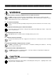
Safety Precautions WARNING 1. Do NOT Use Where Flammable or Explosive Gases or Vapors Are Present. Do NOT operate this product where there are flammable or explosive gases or vapors since this product is not explosion-proof. Operation of the product in such an environment constitutes a safety hazard and may cause a fire or electrical shock. 2. Use Protective Grounding. Always connect the protective grounding to the ground, to prevent electrical shock or fire due to stray current. 3.
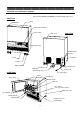
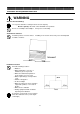
Before Use Parts and Their Functions: Exterior Note: Models IK400W and IM400W are furnished with a glass door.
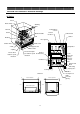
Before Use Parts and Their Functions: Structural Drawings IK Series Flask Flask clamp Shaking table Temperature sensor Link rod Crank Thermal insulation Drawer handle Blower fan Rail Bearing Heater Door guard Shaker motor Guide roller Support roller V belt Evaporator Drive shaft V pulley Photo interrupter Control for rotation speed circuit board detection Photo slit for rotation speed detection Lowpressure piping Defroster solenoid valve Path of flow while defrosting Condenser Capillary tube
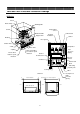
Before Use Parts and Their Functions: Structural Drawings IM Series Flask Flask clamp Shaking table Crank Temperature sensor Drawer handle Blower fan Thermal insulation Support arm Heater Bearing Door guard Shaker motor V belt Evaporator Drive shaft V pulley Lowpressure piping Photo interrupter for rotation speed detection Control circuit board Photo slit for rotation speed detection Defroster solenoid Condenser valve Path of flow while defrosting Capillary tube Cooling fan Drier Compresso
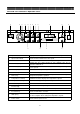
Before Use Parts and Their Functions: Operation Panel ① ② ③ ④ ⑤ ⑦ ⑧ ⑥ ⑨ ⑩ ⑬ ⑪ ⑫ ⑭ ⑯ ⑮ ① Speed indicator Displays the shaking speed in tenths of the revolutions per minute. ② Speed control knob Used to increase and decrease the speed. ③ Lock knob Used to lock the speed control knob to prevent operation error. ④ Door safety lamp ⑤ Door safety key ⑥ Run/stop key Used to start and stop shaking. ⑦ Defrost lamp Lit while defrosting.
Before Use Installation and Preparation Before Use WARNING Do NOT Use Where Flammable or Explosive Gases or Vapors Are Present. Do NOT operate this product where there are flammable or explosive gases or vapors since this product is an arcing device--it produces an arc at power-on--and not explosion-proof. Operation of the product in such an environment may cause a fire or explosion. Use Protective Grounding.
Before Use Installation and Preparation Before Use WARNING Observe the Power Rating. Use a power outlet whose rating meets the electric capacity. Electric capacity: 100 V AC, 9 A for all IK/IM series products Do not use a multiple-outlet adapter. It may cause overheating. Avoid Uneven Surfaces. Install the product on a level surface. Installing on an uneven surface may cause unanticipated accidents or failures.
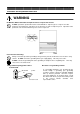
Before Use Installation and Preparation Before Use WARNING Make fine adjustments for precise level installation. After determining where to install the product, use the four adjusters to support this product securely. At that point, also use a level or the like to insure that the product is precisely level. A forward inclination is especially dangerous since the front door may come open and the shelf inside may slide out from the vibration.
Before Use Installation and Preparation Before Use CAUTION Handle the Power Cord Carefully. z Do not entangle the power cord. This will cause overheating and possibly a fire. z Do not bend or twist the power cord, or apply excessive tension to it. This may cause a fire and electrical shock. z Do not lay the power cord under a desk or chair, and do not allow it to be pinched in order to prevent it from being damaged and to avoid fire or electrical shock.
Handling Precautions Installation and Preparation Before Use WARNING Do Not Use Flammable or Explosive Gases or Vapors. Do NOT use flammable or explosive substances, or materials containing such substances. This may cause an explosion and/or fire. The substances that must not be used are listed on Page 32 for reference.
Handling Precautions CAUTION Defrosting During operation at low temperatures, the evaporator becomes heavily frosted. This large amount of frost degrades the freezing power, and the temperature then may not be regulated at the setpoint. The use of samples having a large water content especially accelerates frost on the evaporator--be careful. If you observe that the temperature cannot be regulated at the setpoint, press the defrost key to start defrosting.
Handling Precautions CAUTION Do Not Use Corrosive Samples. z A major part of the internal structure is stainless steel (JIS SUS304 – JIS stands for Japanese Industrial Standards); however, strong acids may corrode it--be careful. z The guard is made of vinyl-chloride rubber, which may be corroded by acids, alkalines, oils, or halide solvents--be careful. Be Careful Not to Get Burned. z Be careful not to get burned.
Operation Placing Flasks Placing Flasks ① Open the door and confirm that shaking has stopped. ② Swing the handle out and turn it clockwise 90 degrees, and then draw out the table. Drawer handle Drawer handle Turn it clockwise 90 degrees. Swing the handle t ③ Hold the tray on the table with both hands and lift it off of the table. Note that the tray does not always have to be removed when placing or taking out flasks.
Operation Placing Flasks ⑥ Attach the clamp ring in its correct position as shown in the figure below. ⑦ Attach rings to all the clamps including those with no flasks. ⑧ Place the tray on the table. Confirm that the tray fixing square-washers at the front and back properly fit the grooves of the tray. Tray fixing squarewasher Tray fixing squarewasher Drawer handle If improperly attached, the tray may slide off while shaking. ⑨ Hold the drawer handle and push the table in slowly.
Operation Placing Flasks Place flasks properly. Place each flask so its center is aligned with the middle of the clamp and so it sits straight up. Must NOT tilt. Centers must be aligned. Do not use a flask that does not fit the clamp. Attach the clamp properly by inserting it to the neck of the clamp. PROPER placement If a clamp ring is not attached properly or if a flask that does not fit the clamp is used, the flask may come loose from the clamp while shaking, thus breaking the flask.
Operation Setting the Temperature ① Press the temperature set key ( The temperature set lamp ( ② Press the left cursor key ( ). The indicator then displays the previous temperature setpoint. ) is lit, indicating that the setting mode is on. ) to move the entry cursor (blinking digit) to the digit you wish to change. Pressing this key moves the cursor in the following sequence.
Pressing the key in this mode does not affect the temperature setpoint at all. ⑧ The occurrence of a problem in temperature control is indicated by an error display. (See Page 21, “Safety Systems and Error Codes.
Operation Operating the Shaker ① For safe operation, keep the “door safety” key ( ) switched on. ② Turn the speed control knob to its leftmost position (SLOW side). (Turn the knob after loosening the lock knob.) ③ Close the door and press the run/stop key ( ). Shaking then starts. Run/stop key status ④ After the shaking starts, slowly turn the speed control knob clockwise to set the speed to the desired level. The speed indicator shows the current speed in tenths of the revolutions per minute (e.g.
Operation Defrosting ① Operation at a low temperature for a long period causes the buildup of frost, which degrades the freezing performance and may disable the temperature from being controlled at the setpoint. In such a case, use the defrosting function. ② Press the defrost key ( ). The defrost lamp then lights up, the internal fan stops, and defrosting starts. ③ Defrosting automatically stops in ten minutes. To stop defrosting before that, press the defrost key ( ) again.
Safety Systems and Error Codes This incubator features safety systems independent of the controller, in addition to the self-diagnostics function of the controller. The table below shows the causes when the safety systems go into effect and the countermeasures to be taken. If an abnormality such as an operational error or equipment failure occurs, the corresponding error code “ErrX” (where X is a number) appears on the operation panel display and a buzzer sounds.
Maintenance Daily Maintenance and Inspection WARNING Do NOT Make Modifications to This Product. Disassembly of the product is strictly prohibited. This may cause an electrical shock since there are high-voltage circuits inside the product. Inspection, maintenance, or repair of the internal circuits and mechanisms should be inquired of the dealer or your nearest sales representative office. Modification is strictly prohibited. This may cause a fire or electrical shock.
Maintenance Daily Maintenance and Inspection ■ Cleaning the Condenser Slats Dust adhering to the condenser slats degrades freezing ability and may prevent the temperature from being controlled at the setpoint. To avoid this, clean the condenser approximately once a month. Cleaning Procedure (1) Detach the louver on the front as follows. Unscrew the round-head M4 screws and detach the louver from the front. The louver hangs on the incubator casing with two hooks. Lift it up and pull it off.
Maintenance Daily Maintenance and Inspection Adjustment of Tension of V Belt Various problems may result from improper tension of the V belt. To avoid these, check and adjust the tension approximately once every six months. Adjustment Procedure (1)Make sure that you unplug the power cord before adjustment. (2)Detach the left and rear covers. V belt Shaker motor (3) Loosen the four bolts that fix the motor mount Motor mount plate plate.
Maintenance Daily Maintenance and Inspection Inspection and Maintenance of Drawer Handle If the shaking table plays back and forth even when the table is pushed in completely and locked, adjustment of the handle hook is needed. If it continues to operate with the play left as is, the life of handle and slide rails are shortened. Adjustment Procedure (1) Loosen the lock nut (1) and slightly tighten (turn clockwise) the lock nut (2).
Maintenance Daily Maintenance and Inspection Inspection of Slide Rails The working surfaces of the steel ball bearings, which are used for the slide rails, become scratched after use. This is normal. When the scratches get to be 5 mm long, replace the slide rails with new ones. The slide rails are Model 301-381 from Nihon ACCURIDE.
Maintenance If Not Using the Product for a Long Period or If Disposing of It WARNING If Not Using for a Long Period If you will not be using the product for a long period, always turn off the power switch on the front and the earth leakage breaker at the rear and shut off the supply power. If disposing If you will be disposing the product, keep it out of the reach of children. For any questions, contact the dealer from whom you purchased the product or the nearest sales representative’s office.
After-Sales Service and Guarantee Requests for Repairs Requests for Repairs Guarantee (given with product) z A certificate of guarantee is given by the dealer If an abnormality occurs, immediately stop the operation, turn off the power switch, and unplug or sales representative’s office from whom you the power cord. Then, contact the dealer from purchased the product.
After-Sales Service and Guarantee Troubleshooting Problem (1) Unusual noise is heard during Causes Set them properly. 2. The tray is not sitting on the table properly, or a flask clamp is not set properly. Failure of drawer handle 3. Improper tension of the V belt Adjust the tension. 1. 2. An adjuster is not touching the floor. The floor or rack is not strong enough to support the incubator. The floor or rack is not level. Adjust the adjuster height. Change the installation location.
Wiring Diagram Note: Common to all models Symbol C ELB H IND M1 M2 MOTER MS MV P PL Part Symbol P-IN-CONT POWER Pt RF S SP TAC TF1 TF2 X Condenser Earth leakage breaker Heater Temperature indicator board Shaker motor Fan Motor control board Door switch Defroster solenoid valve Power plug Speed detector 30 Part Temperature control board Motor power supply board Temperature sensor Freezer Power switch Spark killer TRIAC Transformer Transformer Main relay
Specifications Model IK400 IK400W Temperature control method Draft circulation Shaking method Horizontal back-and-forth Operating temperature range Temperature control accuracy Temperature distribution accuracy 5° to 60°C Shaking speed Approximately 30 to 200 rpm Shaking amplitude 70 mm Const- Heater 500-W iron-chrome wire heater ruction Fan Axial fan with a 14/13-W (50/60 Hz) motor Shaker motor Fully enclosed 60-W motor Interior JIS SUS304 stainless steel Heat insulator Expanded po
Replacement Parts Parts Common to the IK and IM Series Part Code Number. Temperature control board Temperature indicator board Motor control board 1-01-180-0003 P-IN-CONT (for IK-41) 1-01-180-0004 IND 1-01-180-0002 MOTOR Motor power supply board Heater 1-01-180-0001 POWER Temperature sensor 1-16-003-0007 IK41S-40420 Evaporator Specification 500-W iron-chrome wire, 100 V AC Pt 100 Ω (common for IS-42) IN61-20081 TRIAC 1-20-001-0001 400V-30A (with SP) Slit 4-36-001-0002 56-180-t0.
Parts Common to IK Series Part Code Number. Specification Bearings for linkage shaft Support roller 4-18-003-0001 4-18-004-0002 UFL000 E-0835 Guide roller 4-18-004-0002 E-0835 Auxiliary roller 4-18-004-0001 E-0620 Manufacturer KOYO, Japan EASTERN SEIKO, Japan EASTERN SEIKO, Japan EASTERN SEIKO, Japan Parts Common to IM Series Part Code Number.
Reference Dangerous Substances ① Ethylene glycol dinitrate (nitroglycol), glycerine trinitrate (nitroglycerine), cellulose nitrate (nitrocellulose), and other explosive nitrate esters Explosive Explosive Igniting ② Trinitrobenzene, trinitrotoluene, trinitrophenol (picric acid), and other explosive nitro compounds ③ Acetyl hydroperoxide (peracetic acid), methyl ethyl ketone peroxide, benzoyl peroxide, and other organic peroxides Lithium (metal), potassium (metal), sodium (metal), yellow phosphorus, phosp