
Manual


12
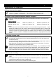
Description and Function of Each Part
Control Panel
AUTO START
FIXED TEMP
AUTO STOP
1
2
3 21
9
10
11
12
13
14 15
16
17
18
19
20
5
6
7
8
℃
PROGRAM
STANDB
Y
END
HEATER
FAN
FUNCTION PROGRAM
MENU
ENTER
CANCEL
SUBMENU
POWER
TROUBLE
DOO
R
4
1
Main Display:
Displays the measured temperature and error code.
2
Sub Display:
Displays the operation and setting information.
3
DOOR lamp:
Lights while the door is opened. (Disabled in this unit.)
4
TROUBLE Lamp:
Blinks when a trouble occurs.
5
FIXED TEMP lamp:
Lights while the fixed temperature operation is running.
Blinks while the choosing operation mode.
6
AUTO STOP Lamp:
Lights while the auto stop operation is running.
Blinks while choosing the operation mode.
7
AUTO START Lamp:
Lights while the auto start operation is running.
Blinks while choosing the operation mode.
8
PROGRAM Lamp:
Lights while the program operation is running.
Blinks while choosing the operation mode.
9
STANDBY Lamp:
Lights while the device is in standby state.
Blinks while the device is in startup wait state.
10
END Lamp:
Blinks at end of the autostop or program operation.
11
HEATER Lamp:
Lights while the heater works.
12
FAN Lamp:
Lights while the fan works.
13
FUNCTION Key:
Starts the function menu.
14
PROGRAM Key:
Starts the program menu.
15
MENU Key:
Starts the operation menu.
16
▼(Down) Key:
Lowers down the setting value.
17
▲(Up) Key:
Rises up the setting value.
18
ENTER Key:
Settles the inputted value/item.
19
CANCEL Key:
Cancels the current inputting.
20
POWER Key:
Turns ON/OFF the power.
21
SUBMENU Key:
Used for operation with the optional accessory.