Forced Convection Constant Temperature Drying Oven Model DKN 302/402/602 612/812/912 Instruction Manual - First Edition - z Thank you for purchasing "Forced Convection Constant Temperature Drying Oven, DKN Series" of Yamato Scientific Co., Ltd. z To use this unit properly, read this "Instruction Manual" thoroughly before using this unit. Keep this instruction manual around this unit for referring at anytime.
Contents Cautions in Using with Safety................................................................ 1 • • • Before Using this unit ............................................................................. 4 • Requirements for Installation......................................................................................... 4 Description and Function of Each Part ................................................. 9 • • • Explanation....................................................
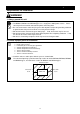
Cautions in Using with Safety Explanation MEANING OF ILLUSTRATED SYMBOLS Illustrated Symbols Various symbols are used in this safety manual in order to use the unit without danger of injury and damage of the unit. A list of problems caused by ignoring the warnings and improper handling is divided as shown below.Be sure that you understand the warnings and cautions in this manual before operating the unit.
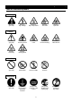
Cautions in Using with Safety Table of Illustrated Symbols Warning Warning, generally Warning, high voltage Warning, high temperature Warning, drive train Warning, explosive Caution, generally Caution, electrical shock Caution, scald Caution, no road heating Caution, not to drench Caution, water only Caution, deadly poison Prohibit, inflammable Prohibit, to disassemble Prohibit, to touch Compulsion, connect to the grounding terminal Compulsion, install on a flat surface Compulsion, discon
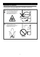
Cautions in Using with Safety Fundamental Matters of "WARNING!" and "CAUTION!" WARNING! Do not use this unit in an area where there is flammable or explosive gas Never use this unit in an area where there is flammable or explosive gas. This unit is not explosion-proof. An arc may be generated when the power switch is turned on or off, and fire/explosion may result. (Refer to page 45 "List of Dangerous Substances".
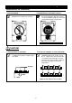
Before Using this unit Requirements for Installation WARNING! 1. Always ground this unit • The DKN302, DKN402and DKN602 types use a 100V power source. • The DKN612, DKN812 and DKN912types use a single-phase 200V power source. Please consult your local electrical contractor for power connecting work. • Be sure to connect the earth wire (the green cable of power cord) to the grounding conductor or ground terminal to prevent accidents caused by electric leakage.
Before Using this unit Requirements for Installation 3. Do not use this unit in an area where there is flammable or explosive gas (Refer to page 45 "List of Dangerous Substances".) • Never use this unit in an area where there is flammable or explosive gas. This unit is not explosion-proof. An arc may be generated when the power switch is turned ON or OFF, and fire/explosion may result.
Before Using this unit Requirements for Installation 4. Do not modify 5. Installation on horizontal surface • Set this unit to the flattest place. Setting this unit on rough or slope place could cause the vibration or noise, or cause the unexpectible trouble or malfunction. • Modification of this unit is strictly prohibited. This could cause a failure. Do not modify To the flattest place CAUTION! 6. Do not make an overload 7.
Before Using this unit Requirements for Installation 8. Choose a correct power distribution board or receptacle • Choose a correct power distribution board or receptacle that meets the unit’s rated electric capacity. Electric capacity: DKN302: DKN402: DKN602: 100V AC, 8.5A 100V AC, 12.5A 100V AC, 14A DKN612: DKN812: DKN912: 1φ200V AC, 8A 1φ200V AC, 12.5A 1φ200V AC, 15.5A NOTE) There could be the case that the unit does not run even after turning ON the power.
Before Using this unit Requirements for Installation 11. Handling of power code • Do not entangle the power cord. This will cause overheating and possibly a fire. • Do not bend or twist the power cord, or apply excessive tension to it. This may cause a fire and electrical shock. • Do not lay the power cord under a desk or chair, and do not allow it to be pinched in order to prevent it from being damaged and to avoid a fire or electrical shock.
Description and Function of Each Part Main Unit DKN302/402/602/612 Exhausted opening Front view Door Cable port Glass window Production plate Door handle Main switch (Earth leakage breaker) Control panel Rear view Power cord DKN612のみ 9
Description and Function of Each Part Main Unit DKN812 Control panel Front view Main switch (breaker) Door Cable port Production plate Caster Door handle Rear view Exhausted opening Power cord 10
Description and Function of Each Part Main Unit DKN912 Front view Control panel Main switch (Earth leakage breaker) Cable port Production plate Door handle Door Caster Rear view Exhausted opening Power cord 11
Description and Function of Each Part Control Panel ⑧ ⑭ ⑨ ⑩ ⑪ ⑫ ⑬ POWER ⑮ ⑯ ③ ⑰ ① ⑱ ② ④ ⑦ ⑤ ⑥ ① START/STOP Key: Starts/stops the operation. ② ▲▼ Key: Uses for rising UP/lowering DOWN the setting value. ③ ENTER Key: Settles the inputted value. ④ FIXED TEMP Key: Chooses the fixed temperature operation. ⑤ TIMER Key: Chooses the timer operation (Quick Auto Stop/Auto Stop/Auto Start). ⑥ PROGRAM Key: Chooses the program operation or program creation mode.
Description and Function of Each Part Characters of the Controller The characters VS4 controller shows are as follows: Character Identifier Name Purpose Used for starting the fixed temperature operation. FiX Fixed Temperature Setting Mode Sv Temperature Setting Used for setting the temperature. AStP Timer Setting Mode Display Represents the setting of quick auto stop or auto stop operation. AStr Timer Setting Mode Display Represents the setting of auto start operation.
Operation Method Operation Mode and Function List All the operation mode of this unit is as follows; No. Name 1. 2. 3. 4. 5. Description Page Fixed Temperature Operation Pressing the FIXED TEMP key enters into the fixed temperature operation setting mode. Pressing it again enters into the temperature setting mode. The "▲▼" are used to set temperature. Pressing the START/STOP key starts or stops operation.
Operation Method Operation Mode and Function List The operation function of this unit is as follows; No. Name 1. Overheating prevention function Description Auto overheating prevention function This function is set to be automatically activated (auto reset) when the temperature exceeds the setting temperature by 12℃.
Operation Method Operation Mode, Function Setting Key, and Characters The operation mode setting and function setting use the key operation and characters show in the following figure.
Operation Method Setting of Overheating Prevention Device The unit has the overheating prevention device (manual reset) that consists of independent temperature measurement circuit, CPU, sensor and output circuit (it shares power source, display, and key input with the controller) in addition to the automatic overheating prevention function (auto reset) in the controller. Setting range/function The unit has failsafe functions against overheating.
Operation Method Fixed Temperature Operation 1. Turn on the power (turn on the breaker in front) Fixed temperature operation procedure The default value is displayed for about four seconds after turning on the power. The screen then displays the initial setting. The current temperature in furnace, operation mode character and setting temperature of overheating prevention device are displayed on respective screens. Measurement temperature screen: Displays the current temperature in furnace.
Operation Method Quick Auto Stop Operation Quick auto stop operation procedure This operation is used to specify the period up to automatic stop, i.e., sets the auto stop timer during operation. 1. Set the time up to stop during fixed temperature operation • Check that the FIXED TEMP lamp lights on and that the unit is under operation. • Press the TIMER key. • The measurement temperature display screen displays the character "tim", which indicates the timer setting.
Operation Method Auto Stop Operation Auto stop operation procedure This operation is used to specify the automatic stop time in the fixed temperature operation. 1. Set stop time ① Press the TIMER key on the initial screen. Press the TIMER key again. The setting temperature display screen displays the character "AstP", which indicates the auto stop operation, with blinking. ② Press the ENTER key. The measurement temperature screen displays the character "SV", which indicates the temperature setting.
Operation Method Auto Stop Operation 3. Stop/terminate timer operation • The operation stops automatically at setting time. • Buzzer continues to sound for about five minutes at operation stop. • The setting temperature screen displays the character "End", which indicates termination of operation, with the FIXED TEMP and AUTO STOP lamps lighting on. Press the START/STOP key to terminate the timer operation mode. The screen returns to the initial setting screen.
Operation Method Auto Start Operation Auto start operation procedure This operation is used to specify the period up to automatic start after power on. 1. Set start time ① Press the TIMER key on the initial screen. Press the TIMER key again. The setting temperature display screen displays the character "Astr", which indicates the auto start operation, with blinking. ② Press the ENTER key. The measurement temperature screen displays the character "SV", which indicates the temperature setting.
Operation Method Auto Start Operation 3. Stop/terminate timer operation • The operation starts automatically at setting time. • Press the START/STOP key for one second to stop or terminate operation. The screen returns to the initial setting screen. To correct or check setting… Changing the setting temperature or time during operation is possible by pressing the TIMER key. Use the "▼▲" to change the setting value. Press the ENTER key respectively after changing the setting.
Operation Method Program Operation This operation is used to change the temperature according to the setting temperature and time. Temp. △ Start △ Stop Time Program types Six patterns of program types maximum can be input. PrG1 1 program pattern using 30 steps maximum can be created. PAt1 PrG2 2 program patterns using 15 steps maximum can be created. PAt2 PAt1 PrG3 3 program patterns using 10 steps maximum can be created.
Operation Method Program Operation Program creation The program pattern below is explained as an example. 1. Program pattern example Temp. 200℃ 100℃ 0℃ Step 1 2 3 4 5 6 7 Temp.(℃) 100 100 150 150 200 200 50 Time(min.) 25 30 15 90 25 180 150 POWER ← Repeat function → The number of steps is not counted. 8 9 50 25 180 100 1. Turn on the power • Turn on the power switch of the unit. • The display on the controller lights on.
Operation Method Program Operation The example shown below explains the method of program registration using PrG3. 4. Register program ① Select PrG3 referring to 3 mentioned above.. ② Input the number of steps, temperature and time for respective steps using the program creation sheet. ③ Press the ENTER key. The PAt1 is displayed with blinking. ("End" is displayed if PrG1 is selected. In this case, go to ⑥) ④ Select the unused pattern from among Pat1, Pat2 and Pat3 using the " ▲▼". ⑤ Press the ENTER key.
Operation Method Program Operation 5. Start program operation • Press the START/STOP key for about one second. The program operation previously set starts. • The PROGRAM lamp lights on and the setting temperature screen displays the step currently under operation. Press the "▼" to check the setting temperature and residual time of step currently under operation on the setting temperature screen. 6. End program operation • Buzzer continues to sound for about five minutes at operation stop.
Operation Method Program Operation Use program repeat function This section explains how to register the program repeat (repeating a program pattern) in program operation. This section explains the registration procedure of program using repeat function in "4. Register program" above.
Operation Method Program Operation Programming Preparation Form 1 (Please use this form by making copies) Register with: PrG1 PrG2 PrG3 PAt1 PAt2 PAt3 No.
Operation Method Program Operation Programming Preparation Form 2 (Please use this form by making copies) Register with: PrG1 PrG2 PrG3 PAt1 PAt2 PAt3 No. Date Project Name Programmer Input Value Temperature (℃) Time (min.
Operation Method Other Functions Use calibration offset function Calibration offset is a function which corrects the difference between the temperature in furnace and that of controller (sensor temperature) if arises. The function parallel corrects the difference either to the plus or minus side within the whole temperature range of unit. The function can be set or cancelled by the SUBMENU key. Corrected temp. to plus side Current temperature Corrected temp.
Handling Precautions WARNING! If a problem occurs If smoke or strange odor should come out of this unit for some reason, turn off the power key right away, and then turn off the circuit breaker and the main power. Immediately contact a service technician for inspection. If this procedure is not followed, fire or electrical shock may result. Never perform repair work yourself, since it is dangerous and not recommended.
Handling Precautions Setting of sample Since the withstand load of the attached shelf plate is about 15kg per one plate, do not set heavier sample than 15kg. When setting several sample, set them as dispersed as possible. Too much sample setting could cause the improper control of the temperature. For keeping the proper temperature, keep more than 30% space against whole size of the shelf plate, and set the sample.
Maintenance Method Daily Inspection and Maintenance For the safety use of this unit, please perform the daily inspection and maintenance without fail. Using the city water to this unit might attach dirt. Do inspect and maintain this point while performing daily inspection and maintenance. WARNING! • • • Disconnect the power cable from the power source when doing an inspection or maintenance unless needed.
Long storage and disposal When not using this unit for long term / When disposing CAUTION! When not using this unit for long term… • Turn off the power and disconnect the power cord. WARNING! When disposing… • Keep out of reach of children. • Remove the door and driving parts. • Treat as large trash. Environmental protection should be considered We request you to disassemble this unit as possible and recycle the reusable parts considering to the environmental protection.
In the Event of Failure… Safety Device and Error Code This unit has an automatic diagnosis function built in the controller and safety devices independent of the controller. The table below shows the cause and the solution method when the safety device operates. Error Code: When an abnormal condition occurs, an error code appears and the alarm lamp lights in the controller, the buzzer sounds simultaneously. Record the error code and turn off the power of device immediately.
In the Event of Failure… Trouble Shooting Before call us... Condition The device does not start when turning on the power switch. Temperature fluctuates during the operation. Possible Causes • Power plug is not connected to the receptacle correctly. • Power failure. • Too much samples. • Wind from air conditioner directly blows. • The change of ambient temperature is remarkable. • Samples are too moist. • The power supply voltage is lower than the proper value.
After Service and Warranty In Case of Request for Repair If the failure occurs, stop the operation, turn OFF the power switch, and unplug the power plug. Please contact the sales agency that this unit was purchased, or the Yamato Scientific's sales office. < Check following items before contact > ◆ Model Name of Product See the production plate attached to this unit.
Specification DKN302 Method Temperature control range Temperature adjustment accuracy Temperature distribution accuracy DKN402 DKN602/612 Forced circulation DKN812 DKN912 0 to 260℃ (Ambient temp.: 23℃, No load, Damper: full closed) ±1℃ (Middle of furnace, Set temp.: 210℃, Damper: full closed) ±2.5℃ (Set temp.: 210℃, Damper: full closed) (Room temp. to 210℃) Temperature rise time Approx. 75min. Approx. 60min.
Wiring Diagram DKN302/402/602 ELB TM1 1 AC100V X FM 1 1 2 CN5 ・ 3 CN8 1 CN9 ・ 2 H 2 1 3 SSR 2 CN2 3 18 1 1 18 CN2 18 1 PIO 1 CN1 2 CT 4 3 4 CN1 1 TB1 2 1 ・ 3 2 ・ + - 3 + ・ - CN4 TB2 1 2 4 ・ TH1 TH2 5 X Symbol ELB TM1 H X FM SSR Part name Earth leakage breaker Terminal block Heater Main relay Circulation fan Breakerless relay Symbol CONT PIO TH1 TH2 CT 40 ・ 6 ・ Part name Control board Display circuit board Sensor for control Sensor for overheating prevent
Wiring Diagram DKN612 ELB TM1 1 AC200V X FM 1 1 2 CN5 ・ 3 CN8 1 CN9 ・ 2 H 2 1 3 SSR 2 CN2 3 18 1 1 18 CN2 18 1 PIO 1 CN1 2 CT 4 3 4 CN1 1 TB1 2 1 ・ 3 2 ・ + - 3 + ・ - CN4 TB2 1 2 4 ・ TH1 TH2 5 X Symbol ELB TM1 H X FM SSR Part name Earth leakage breaker Terminal block Heater Main relay Circulation fan Breakerless relay Symbol CONT PIO TH1 TH2 CT 41 ・ 6 ・ Part name Control board Display circuit board Sensor for control Sensor for overheating prevention Curr
Wiring Diagram DKN812 ELB TM1 1 AC200V X FM 2 H2 3 18 1 18 1 CN1 CN9 2 CT H1 1 1 2 CN5 CN8 3 18 2 1 SSR 4 X 3 4 CN1 1 CN2 18 1 2 CN2 1 3 TB1 2 3 1 2 1 TB2 2 3 CN4 4 5 6 1 PIO + + - TH1 TH2 CONT Symbol ELB TM1 H1/H2 X FM SSR Part name Earth leakage breaker Terminal block Heater Main relay Circulation fan Breakerless relay Symbol CONT PIO TH1 TH2 CT 42 Part name Control board Display circuit board Sensor for control Sensor for overheating prevention Current transformer
Wiring Diagram DKN912 ELB TM1 1 1 AC200V FM1 FM2 2 CN5 3 X 2 1 CN1 2 CT H1 H2 1 18 18 1 1 18 CN1 CN8 CN2 CN9 1 18 3 2 1 SSR 4 3 4 1 2 CN2 3 PIO 1 TB1 2 3 1 2 3 4 CN4 1 TB2 2 + + - TH1 TH2 5 X Symbol ELB TM1 H1/H2 X FM1/FM2 SSR Part name Earth leakage breaker Terminal block Heater Main relay Circulation fan Breakerless relay Symbol CONT PIO TH1 TH2 CT 43 6 CONT Part name Control board Display circuit board Sensor for control Sensor for overheating prevention Curren
Replacement Parts Table DKN302/402/602 Part Name Specification Manufacturer Code No. Sensor LCK-M1-2000-Y K single Yamato Scientific 1160030049 VS4 PLANAR board VS4 Yamato Scientific 1020000048 VS4 display circuit board VS4 Yamato Scientific 1020000051 Tough card 50mm Yamato Scientific 1130000009 Main relay AHE1254 100V/120V Matsushita 2050000019 SSR TRS5225 Toho Denshi 2160000035 Power cord kit 2.
Reference List of Dangerous Substances Never use explosive substances, flammable substances and substances that include explosive or flammable ingredients in this unit.
Responsibility Please follow the instructions in this document when using this unit. Yamato Scientific has no responsibility for the accidents or breakdown of device if it is used with a failure to comply. Never conduct what this document forbids. Unexpected accidents or breakdown may result in. Note ◆ The contents of this document may be changed in future without notice. ◆ Any books with missing pages or disorderly binding may be replaced.