Instrument Drying Oven Model DG400 Second edition ●Thank you very much for purchasing this Yamato DG400 instrument drying oven. ●Please read the “Operating Instructions” and “Warranty” before operating this unit to assure proper operation. After reading these documents, be sure to store them securely together with the “Warranty” at a handy place for future reference. Warning:Before operating the unit, be sure to read carefully and fully understand important warnings in the operating instructions.
Table of contents 1.Safety precautions .................................................................. 1 Explanation of pictograms ............................................................. 1 List of symbols ....................................................................... 2 Warning・Cautions ................................................................... 3 2. Before operating the unit............................................................ 4 Precautions when installing the unit .........
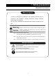
1. Safety precautions Explanation of pictograms About pictograms A variety of pictograms are indicated in this operating instruction and on products for safe operation. Possible results from improper operation ignoring them are as follows. Be sure to fully understand the descriptions below before proceeding to the text. Warning Indicates a situation which may result in death or serious injury (Note 1.
1.
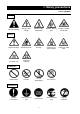
1. Safety precautions Warning・Cautions Warning Never operate the unit in an atmosphere containing flammable or explosive gas Never operate the unit in an atmosphere containing flammable or explosive gas. Otherwise, an explosion or a fire may result since the unit is not explosion-proof. See section “13. List of dangerous materials” on page 37. Be sure to connect the ground wire. Be sure to connect the ground wire correctly. Otherwise, electrical leak may result and cause an electrical shock or a fire.
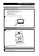
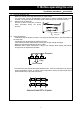
2. Before operating the unit Precautions when installing the unit 1. Carefully select an installation site. Take special care not to install the unit at a place described below: ・ Uneven surfaces or dirty surfaces ・ Where flammable gas or corrosive gas exists ・ Where the ambient temperature is 35℃ or more ・ Where temperature changes severely ・ Where humidity is high ・ Where subject to direct sunlight ・ Where vibration is severe Install this unit at a place with spaces shown below.
2. Before operating the unit Precautions when installing the unit 4. Secure sufficient ventilation for the unit. Do not operate the unit when its side panels and vent holes are blocked. Internal temperature of the unit will rise degrading the performance and an accident, a malfunction or a fire may result. 5. Do not operate the unit at such a place that may subject to splash. Do not operate the unit at such a place that may subject to splash.
2. Before operating the unit Precautions when installing the unit 7. Be sure to connect the power plug to the dedicated power distribution panel or a wall outlet. Use a power distribution panel or a wall outlet that meets the electrical capacity of the unit. Electrical capacity: DG400 AC100V 10.
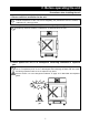
2. Before operating the unit Installation procedures・precautions (1) Select an installation site. ・Make sure that all of four legs are securely on a flat surface. ・Two legs on the unit front are adjustable. Adjust them so that the installed unit will not be unstable. Turning the adjuster clockwise raises it and turning it anti-clockwise lowers it. (2) ・Placement of the drain pan. Be sure to place a drain pan to receive water generated during the drying process. Drain pan (3) Install shelf boards.
2. Before operating the unit Installation procedures・precautions (4) Do not put an instrument on the bottom of the internal bath. ・Operating the unit with a fixing directly put on the bottom of the internal bath might degrade its temperature characteristics. This also may cause corrosion, damage or rust of the internal bath. Never put any fixing on the bottom surface. ・When putting instruments, take care not to allow them touching the heater, the sensor or other devices that are installed on the bottom.
3.
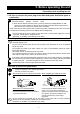
3. Names and functions of parts Operation panel MEASURED TEMP. ⑤ ⑥ ℃ ④ ⑦ HEATER RUN SET TEMP. ③ RUN TIMER ① STOP SUB MENU ② No. Name Operation/action ① RUN/STOP key Used for starting/stopping operation. ② ▼▲ keys Used for selecting settings. ③ TIMER key Key for selecting timer operation settings. Quick auto stop operation, auto stop operation or auto start operation can be selected.
3. Names and functions of parts Explanation of characters Characters on the controller are explained in this section. Characters Identifier Name Application AStP Auto stop setting Used for setting auto stop operation. AStr Auto start setting Used for setting auto start operation. Displayed when timer operation has End Time up ended. See page 17, 19.
4. Operating procedures List of operation modes and functions Operation modes of the unit are as shown below: № Name Description Page Turning the ELB on to enter the operation setting mode. 1 Fixed temperature Proceed to temperature setting that uses ▼▲ keys. operation Pressing the RUN/STOP key long starts the operation and P.16 pressing it long again stops operation. Used when you want to “stop fixed temperature operation being performed automatically in several hours.
4. Operating procedures List of operation modes and functions Functions of the unit are as shown below: Name № Description Page Automatic overheat prevention function: This function is linked to the unit set temperature and has been set to so that it is automatically activated (returned automatically) at a temperature 12℃ higher than the set temperature in the bath.
4. Operating procedures Operation mode・function setting keys and characters Key operations and characters in the diagram below are used for operation mode and function settings. ELB ON Fixed temp. operaiton Timer operation Functional setting Long press TIMER Temperature setting ▲ Setting lock function Power outage compensation function AStr cAL LocK Pon Time setting Compensation setting Lock setting Power outage compensation setting Auto stop Auto start Fixed temp.
4. Operating procedures Operating procedures (settings for overheat prevention device) As a safety measure for preventing overheat, a hydraulic overheat prevention device (manual return) is installed. Temperature setting range and functions The temperature setting range for the standalone overheat prevention device is “50℃~120℃.
4. Operating procedures Operating procedures (fixed temperature operation) How to start fixed temperature operation 1.Turn the ELB ON. (Turn the ELB to “ON.”) When the ELB is turned ON, the initial values will be displayed for about four seconds, then the initial screen will appear and the current bath temperature and the previous set temperature are displayed on each of the indicators. MEASURED TEMP.
4. Operating procedures Operating procedures (quick auto stop operation) Used when you want to “stop fixed temperature operation being performed automatically in several hours. Quick auto stop operation is a function to enable auto stop timer setting during operation. Procedures for quick auto stop operation 1. Setting before stop during fixed Make sure that the RUN lamp is illuminated to indicate the unit is in operation. MEASURED TEMP. Press the TIMER key.
4. Operating procedures Operating procedures (quick auto stop operation) When you want to correct set temperature or set time, or change settings When you want to change settings, press the ▼▲ keys on the current screen to enter the setting mode where you can change settings. Blinking stops in three seconds after change and setting is completed. Note, however, that temperature changes after timer activation are counted also while temperature is changing.
4. Operating procedures Operating procedures (auto stop operation) This mode automatically stops fixed value operation after a certain time from its start set with the timer. Procedures for auto stop operation 1. Setting a stop time ① After confirming the temperature you want is set, press the TIMER key to display characters AStP on the measured temperature screen that indicate auto MEASURED TEMP. ℃ stop operation. The set time is displayed on the set temperature HEATER RUN SET TEMP.
4. Operating procedures Operating procedures (auto stop operation) When you want to correct set temperature or set time, or change settings When you want to change settings, press the ▼▲ keys on the current screen to enter the setting mode where you can change settings. Blinking stops in three seconds after change and setting is completed. Note, however, that temperature changes after timer activation are counted also while temperature is changing.
4. Operating procedures Operating procedures (auto start operation) This mode automatically starts fixed value operation after a certain time from its start set with the timer. However, operation does not stop automatically but needs to be stopped manually. Procedures for auto start operation 1. Setting an operation start time ① After confirming the temperature you want is set, press the TIMER key to display characters AStr on the measured temperature screen that indicate auto start operation.
4. Operating procedures Operating procedures (auto start operation) When you want to correct set temperature or set time, or change settings When you want to change the set temperature during timer counting, press the ▼▲ keys during that status to switch the set temperature screen to the set temperature input mode, which blinks to enable change of the set temperature with the ▼▲ keys.
4. Operating procedures Useful functions (calibration offset function) Using the calibration offset function Calibration offset function compensates any differences between the target temperature in the bath and the control temperature of the controller (sensor temperature.) The function can compensate in parallel to either plus or minus side for the whole temperature band of the unit. The lock can be set or released with the SUBMENU keys. The temperature is set at “0” on shipping from the factory.
4. Operating procedures Useful function (setting lock function) Using the lock function This function locks the set operation status. The temperature is set at “off” on shipping from the factory. ① the sub menu mode. MEASURED TEMP. Press the TIMER key (SUBMENU key) several times ℃ to select the characters Lock setting lock function. HEATER RUN SET TEMP. RUN TIMER Press the TIMER key (SUBMENU key) long to enter that indicate the STOP SUB MENU ② “Off” is displayed on the set temperature screen.
4. Operating procedures Useful function (power outage compensation function) Using the power outage compensation function The power outage compensation function returns the main unit operation to the resume status after recovery from power outage, or keeps the current stop status. The function is set at “on” on shipping from the factory. ① the sub menu mode. MEASURED TEMP. Press the TIMER key (SUBMENU key) several times ℃ to select the characters Pon setting lock function. HEATER RUN SET TEMP.
5. Cautions on handling Warning 1. About handling of flammable or combustible solution The unit is not explosion proof. Take special care for handling instruments on which explosive materials, combustible materials or materials containing these are attached. Flammable or combustible solution will evaporate when left at a room temperature (or at a lower temperature for some types of solutions) and may be ignited and explode from switches, lights and other ignitable sources.
5. Cautions on handling Caution 1.Do not step on the unit. Do not step on the unit. Otherwise, the unit may trip over or be damaged resulting a personal injury or a malfunction. 2.Do not put or drop an object on the unit. 2.Do not put or drop an object on the unit. Since the unit contains high precision devices, vibrations or shock may cause a malfunction. 3. When a thunder is heard. When a thunder is heard, turn the ELB on the main unit off then turn the main power off immediately.
5. Cautions on handling Caution 9. About installation of shelf boards and instruments Correctly place shelf boards and samples according to Installation procedures・precautions on page 7. If these are not placed correctly, the unit will be unable to perform correctly as well as an accident or a malfunction may result. 10. Do not attempt to do anything other than specified in this operation manual. Do not attempt to do anything other than specified in this operation manual.
6. Maintenance procedures Daily inspection/maintenance Be sure to perform daily inspection and maintenance to assure reliable operation of the unit. Warning ● Be sure to pull out the power cord unless necessary before trying to do inspection and maintenance works. ● Start these works after the device has returned to the normal temperature. ● Never try to disassemble the unit. Caution ● Wipe off any dirt with a tightly wrung soft cloth.
7. When the unit is not to be used for a long time or when disposing When the unit is not to be used for a long time or when disposing Caution Warning When the unit is not going to be used for a long When disposing the unit time ●Do not leave the unit in the area where children may have access. ●Turn the ELB to off and pull out the power ●Be sure to remove handles before disposing cord. the unit to prevent the doors from locking. ●In general, dispose the unit as a bulky waste.
8. Troubleshooting Safety device and error codes The unit has the self diagnostic function with a controller and a separate safety device. Table below shows possible causes and measures when the safety device is triggered. [Error codes] When a functional or mechanical abnormality occurs, an error code will be displayed on the control panel. When an abnormality occurs, confirm the error code and immediately stop operation.
8. Troubleshooting When a malfunction is suspected If any of the symptoms below occurs Symptom Turning the ELB to on will not activate the unit. Temperature does not rise. Check ● If the power cord is connected to the power supply securely. ● If power outage is occurring. ● If the standalone overheat prevention device is working. ● If the set temperature is below that in the device. ● If the power supply voltage has declined. ● If the ambient temperature is low.
9. After sales service and warranty When requesting a repair When requesting a repair If any trouble occurs, immediately stop operation, turn the ELB off, pull out the power plug and contact your dealer or our sales office. Information necessary for requesting a repair ● Model name of the product ● Serial number ● Date (y/m/d) of purchase ● Description of trouble See the warranty card or the nameplate installed on the unit. See “3. Names and functions of parts on page 9.
10. Specifications Model DG400 Room temperature +5℃~70℃ Specifications Safety device Control assembly Configuration Operating temperature range Inner material Stainless steel SUS304 Observation window Standard glass 3mm W250 x H300 mm Heater SUS pipe heater 1.
11.
12. List of replacement parts Components of DG400 Symbol Part name Code No. Specifications T Heater LT00008800 TH Sensor 1-16-003-0049 OH EGO thermostat LT00008745 55.13225.
13. List of dangerous materials Never use an explosive substance a flammable substance or a substance containing Explosive substance Explosive substances Explosive substance them for this device.
14. Standard installation manual *Install the product according to the following: (Confirm separately for optional items or special specifications) Installation Judg Model Serial number Date Installation mgr. mgr.
Limited liability Be sure to use the unit strictly following the handling and operating instructions in this operating instruction. Yamato Scientific Co., Ltd. assumes no responsibility for an accident or a malfunction caused by use of this product in any way not specified in this operating instruction. Never attempt to perform matters prohibited in this operation instruction. Otherwise, an unexpected accident may result.