Coolline Model CLS301/400/600 Instruction Manual - Third Edition - z Thank you for purchasing "Coolline, CLS Series" of Yamato Scientific Co., Ltd. z To use this unit properly, read this "Instruction Manual" thoroughly before using this unit. Keep this instruction manual around this unit for referring at anytime. WARNING!: Carefully read and thoroughly understand the important warning items described in this manual before using this unit. Yamato Scientific Co. LTD.
Contents Cautions in Using with Safety................................................................ 1 • • • Before Using This Unit ........................................................................... 4 • • Requirements for Installation......................................................................................... 4 Installation Procedure....................................................................................................
Specification .......................................................................................... 45 Wiring Diagram...................................................................................... 46 • • • CLS300 ....................................................................................................................... 46 CLS400 ....................................................................................................................... 47 CLS600 ...................
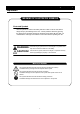
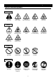
Cautions in Using with Safety Explanation MEANING OF ILLUSTRATED SYMBOLS Illustrated Symbols Various symbols are used in this safety manual in order to use the unit without danger of injury and damage of the unit. A list of problems caused by ignoring the warnings and improper handling is divided as shown below.Be sure that you understand the warnings and cautions in this manual before operating the unit.
Cautions in Using with Safety Table of Illustrated Symbols Warning Warning, generally Warning, high voltage Warning, high temperature Warning, drive train Warning, explosive Caution, generally Caution, electrical shock Caution, scald Caution, no road heating Caution, not to drench Caution, water only Caution, deadly poison Prohibit, inflammable Prohibit, to disassemble Prohibit, to touch Compulsion, connect to the grounding terminal Compulsion, install on a flat surface Compulsion, discon
Cautions in Using with Safety Fundamental Matters of "WARNING!" and "CAUTION!" WARNING! Do not use this unit in an area where there is flammable or explosive gas Never use this unit in an area where there is flammable or explosive gas. This unit is not explosion-proof. An arc may be generated when the POWER switch is turned on or off, and fire/explosion may result. (Refer to page 50 "List of Dangerous Substances".
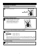
Before Using This Unit Requirements for Installation 1. Always ground this unit • Be sure to connect the earth wire (the green cable of power cord) to the grounding conductor or ground terminal to prevent accidents caused by electric leakage. • Do not connect the earth wire to gas or water pipes. If not, fire disaster may be caused. • Do not connect the earth wire to the ground for telephone wire or lightning conductor. If not, fire disaster or electric shock may be caused.
Before Using This Unit Requirements for Installation 4. Do not modify • Modification of this unit is strictly prohibited. This could cause a failure. 改造 Modification 5. Installation on horizontal surface • Place this unit as flat a place as possible. If the rubber feet (model CLS301) or casters (models CLS400/600) are not in uniform contact with the floor surface, noise or vibration may result. Additionally, the unit may cause a problem or malfunction. 6.
Before Using This Unit Requirements for Installation 8. Handling of power code • Do not entangle the power cord. This will cause overheating and possibly a fire. • Do not bend or twist the power cord, or apply excessive tension to it. This may cause a fire and electrical shock. • Do not lay the power cord under a desk or chair, and do not allow it to be pinched in order to prevent it from being damaged and to avoid a fire or electrical shock.
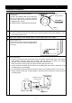
Before Using This Unit Installation Procedure 1 ボタン位置(高) Button position: high Release the stopper lock of the casters. (CLS400/600) Push down the stopper button of the casters as shown in the right figure. It will be unlocked. (Only the two casters on the front side of the unit are equipped with a caster.) The model CLS301 is equipped with rubber feet.
Before Using This Unit Installation Procedure 6 Connecting the power. Confirm that the leakage breaker and the POWER switch are turned "OFF", and then plug into an outlet. 7 Installing the external water tank (optional accessory) Install the external water tank in a higher place than the unit. If it is installed in a lower place, the flow rate may drop or air bleeding may not be carried out smoothly when pouring the circulating fluid for the first time. 8 Pour the circulating fluid into the water tank.
Description and Function of Each Part Main Unit Front view Rating notice sticker Control panel POWER switch Earth leakage breaker Caster (Two front casters have stopper) Rear view Temperature output terminal Discharge port (OUT) Air release valve Return port (IN) Drain cock Power cord 9
Description and Function of Each Part Control Panel ④ ⑧ ⑤ ⑥ ⑨ ⑦ ① ③ ② ⑩ No. Name Function ① RUN/STOP Key Used for operation Start/Stop. ② ▲▼ Key Selects setting value. ③ TIMER Key (SUB MENU Key) Selection key for timer operation. Selects Quick Auto Stop operation, Auto Stop operation, and Auto Start operation. Carries out the settings for Calibration Offset Temperature, Key rock function, and power failure compensation function. ④ FIXED TEMP Lamp Lights during Fixed Temp. operation.
Description and Function of Each Part Operation Monitor ① ③ ⑤ ② No. Name ④ Function ① REFRIGERATOR ERROR Lamp Lights when the refrigerator is over-lorded. ② ERROR Lamp Lights when abnormality is found with the Temperature adjuster. ③ REFRIGERATOR Lamp Lights when the refrigerator is running. ④ PUMP Lamp Lights when the pump is running. ⑤ POWER Switch Executes Power ON/OFF.
Description and Function of Each Part Characters of the Controller The characters controller shows are as follows: Character Identifier Name Purpose AStP Auto Stop Setting Used for setting the auto stop operation. AStr Auto Start Setting Used for setting the auto start operation. End Time-up Displayed when timer operation is ended. cAL Calibration Offset Setting LocK Key Lock Pon Power failure compensation setup Accm Addition time Used for inputting the calibration offset temperature.
Operation Method Operation Mode and Function List The operation modes of this unit are as follows; Name Description Page Fixed Temperature Operation Set the Temperature by ▼▲ key. Start/Stop operation by pressing RUN/STOP key. 16 Quick Auto Stop Operation Used in case that the operation needs to be stopped a few hours after setting. The time to the operation stop can be set up by pressing TIMER key during the Fixed Temp. operation. The time can be set by ▼▲ key.
Operation Method Operation Mode and Function List The operation functions of this unit are as follows; Name Description Page Calibration offset function This calibration offset function is for calibrating the difference occurred between the required in- bath temperature and control temperature (sensor temperature) of the controller. This unit can be calibrated toward either plus side or minus side of the whole temperature range.
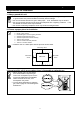
Operation Method Operation Mode, Function Setting Key, and Characters The operation mode setting and function setting use the key operation and characters show in the following figure. Breaker ON POWER switch ON Timer operation Fixed Temp. operation Function setting 4 sec.
Operation Method Fixed Temperature Operation In this mode, the unit starts to operate by pressing RUN/STOP key and continues operating at the set temperature until RUN/STOP key is re-pressed, as shown in the figure below. 温度(℃) TEMP. SV:温度設定値 SV: Set Temp. SV スタート/ストップ key: キーONON RUN/STOP Fixed temperature operation procedure スタート/ストップ key: キーOFF RUN/STOP OFF 時間(t) TIME 1.
Operation Method Fixed Temperature Operation 3. Start operation • Press RUN/STOP key for a second. • FIXED TEMP. lamp will be lit and operation will start. • When the refrigerator starts operating, REFRIGERATOR lamp will be lit. 4. Stop operation • Press RUN/STOP key for a second. • FIXED TEMP. lamp will be put out and operation will stop. • The screen will return to the initial setting screen. To correct or check setting… To change the setting value, press ▼▲ key.
Operation Method Quick Auto Stop Operation Quick auto stop operation procedure This operation is used to specify the period up to automatic stop, i.e., sets the auto stop timer during operation. 1. Enter the quick auto stop mode during fixed temperature operation • Confirm that the FIXED TEMP. lamp is lit, and it is under operation. • Press TIMER key. • AUTO STOP lamp will blink. 2. Set the timer • Setting value will blink at setting temperature screen. • Set the proper time by ▼▲ key.
Operation Method Quick Auto Stop Operation 4. Stop/terminate timer operation • The operation will be stopped automatically at the setting time. • The character "End" which tells that the operation is ended will blink at the setting temperature screen, while FIXED TEMP. lamp and AUTO STOP lamp are on. • End the timer operation mode by pressing RUN/STOP key for a second. • The screen will return to initial setting screen. 5.
Operation Method Auto Stop Operation In this mode, the unit automatically comes to a stop after the set period passes away from the start of fixed-value operation according to timer setting, as shown in the figure below. TEMP. 温度(℃) PV SV:温度設定値 SV: Set Temp. PV:温度表示値 PV: Current Temp. SV RUN/STOP key: ON スタート/ストップ キーON Auto stop operation procedure Timer Operation タイマ起動 タイマスタート Timer starts タイムアップ Time-up 時間(t) TIME RUN/STOP OFF スタート/ストップkey: キーOFF 1.
Operation Method Auto Stop Operation 3. Select auto stop operation • Press TIMER key, and display the character "AStP" which means auto stop operation. • Measured temperature screen: "AStP" which means auto stop operation is displayed. • Setting temperature screen: The time which is set just before is displayed. 4. Set the timer • Setting value will blink at setting temperature screen. • Set the proper time by ▼▲ key. The setting value will be smaller by ▼ key, and larger by ▲ key.
Operation Method Auto Stop Operation 6. Stop/terminate timer operation • The operation will be stopped automatically at the setting time. • The character "End" which tells that the operation is ended will blink at the setting temperature screen, while AUTO STOP lamp is on. • End the timer operation mode by pressing RUN/STOP key for a second. • The screen will return to initial setting screen. 7. To suspend auto stop operation • End timer operation mode by pressing RUN/STOP key for a second.
Operation Method Auto Start Operation In this mode, the unit automatically starts to operate after the set period passes away from the start of fixed temperature operation according to timer setting, as shown in the figure below. However, it does not automatically come to a stop and must be manually deactivated. 温度(℃) TEMP. PV SV:温度設定値 SV: Set Temp. PV:温度表示値 PV: Current Temp.
Operation Method Auto Start Operation 3. Select auto start operation • Press TIMER key, and display the character "AStr" which means auto start operation. • Measured temperature screen: "AStr" which means auto start operation is displayed. • Setting temperature screen: The time which is set just before is displayed. 4. Set the timer • Setting value will blink at setting temperature screen. • Set the proper time by ▼▲ key. The setting value will be smaller by ▼ key, and larger by ▲ key.
Operation Method Auto Start Operation 6. Stop/terminate timer operation • After timer operation, it will start operation at the setting time. At this time, AUTO START lamp is still on. • To stop/terminate timer operation, press RUN/STOP key for a second, then timer operation mode will end. • The screen will return to the initial screen. 7. To suspend auto start operation • End timer operation mode by pressing RUN/STOP key for a second. • The screen will return to initial setting screen.
Operation Method Calibration Offset Function Calibration offset is a function which corrects the difference between the temperature in bath and that of controller (sensor temperature) if arises. The function parallel corrects the difference either to the plus or minus side within the whole temperature range of unit. The function can be set or cancelled by the SUB MENU key. "0" is set at factory shipment. Corrected temp. to minus side Current temperature Corrected temp.
Operation Method Lock Function Lock function that makes operation setting unchangeable. ① Press SUB MENU key for 4 seconds. Then by pressing SUB MENU key, select the character "LocK" which means setting value lock, and press RUN/STOP key. ② The display "oFF" will light at the setting temperature screen. By changing the display to "on" with ▼▲ key, the setting value will be locked. Press SUB MENU key for a few seconds to complete the setting. ③ To cancel the lock function, press SUB MENU key for 4 seconds.
Operation Method Power Failure Compensation Function This is the setting that can start the operation with the former setting in case of electric outage. ① Press SUB MENU key for 4 seconds. Then by pressing SUB MENU key, select the character "Pon" which means power failure compensation, and press RUN/STOP key. ② The display "oFF" will light at the setting temperature screen. By changing the display to "on", power failure compensation operation is set.
Operation Method Addition Time Function Displays the time length that the controller is plugged. ① Press SUB MENU key for 4 seconds. Then by pressing SUB MENU key, select the character "Accm" which means addition time, and press RUN/STOP key. ② The time length that the controller is plugged is displayed at the setting temperature screen. Press SUB MENU key for a few seconds. The screen will returns to the initial screen.
Operation Method Temperature Output Terminal Precautions • Operate this product according to the procedure described in this instruction manual. Failure to follow the operation procedure described herein may result in a problem. The guarantee will not apply if you operate the product in the wrong manner. CAUTION! • Turn off the breaker before connecting the cables. • Connect a recorder or another appliance of 600 W or less in input impedance to the temperature output terminal.
Operation Method Temperature Output Terminal Specification • The voltage (DC) corresponding to the measured temperature is output. • Output temperature range: CLS301 -15 to 35℃, CLS400/600 -20 to 35℃ • Output voltage: 4 to 20mA DC Temperature Output (ANALOG) • Load: 600Ω or bellow • Resolution: ±1℃ • Connection: M4 screw terminal block CLS301 Temperature Output 35 Temp. 22.5 10 -2.5 -15 4 8 12 16 20 Output Voltage (mA) CLS400/600 Temperature Output 35 Temp. 21.25 7.5 -6.
Operation Method Cooling curve, cooling capacity curve (reference data) The graphs show the cooling and cooling capacity curves of each model below. Use the values just for reference because they depend on the sample volume, the ambient temperature, etc. CLS300冷却曲線 室温20℃ CLS301 heating and cooling curves at a room temperature of 20°C 30.0 温度(℃) Temperature (°C) 20.
Operation Method Cooling curve, cooling capacity curve (reference data) CLS400冷却曲線 CLS400 heating and cooling curves at室温20℃ a room temperature of 20°C 30.0 温度(℃) Temperature (°C) 20.0 Fluid quantity in external water tank: 外部槽液量 エチレングリコール50%5L 5 litters of ethylene glycol 50% Fluid quantity in external water tank: 外部槽液量 エチレングリコール50%10L 10 litters of ethylene glycol 50% 10.0 Fluid quantity in external water tank: 外部槽液量 エチレングリコール50%20L 20 litters of ethylene glycol 50% 0.0 -10.0 -20.
Operation Method Cooling curve, cooling capacity curve (reference data) CLS600 heating and CLS600冷却曲線 cooling curves 室温20℃ at a room temperature of 20°C 30.0 温度(℃) (°C) Temperature 20.0 Fluid quantity in external water tank: 外部槽液量 エチレングリコール50%10L 10 litters of ethylene glycol 50% Fluid quantity in external water tank: 外部槽液量 エチレングリコール50%20L 20 litters of ethylene glycol 50% 10.0 Fluid quantity in external water tank: 外部槽液量 エチレングリコール50%30L 30 litters of ethylene glycol 50% 0.0 -10.0 -20.
Operation Method Cooling curve, cooling capacity curve (reference data) CLS冷却能力曲線 CLS cooling capacity curves 1000 900 CLS600 800 CLS400 700 Cooling 冷却能力(W) capacity (W) 600 500 400 CLS300 CLS301 300 200 室温temperature: :20℃20°C Room 使用循環液 :エチレングリコール50% Used circulating fluid: Ethylene glycol 50% 外部水槽 :CTB-12A(12L) External water tank: CTB-12A (12L) 電源 :AC100V 50Hz Power supply: 100V AC 50Hz 100 0 -40 -30 -20 -10 0 10 Temperature (°C) 温度(℃) 35 20 30 40 50 60
Operation Method Nybrine freezing temperature and viscosity (reference data) ナイブラインZ 1,Zof 1-KおよびナイブラインNFPの凍結温度 Freezing temperatures Nybrine Z1, Z1-K, and Nybrine NFP 0 0 -10 ナイブラインNFP Nybrine NFP -20 -20 Nybrine Z1,1,Z Z1-K ナイブラインZ 1 -K -30 -30 -40 -40 -50 -50 0 10 20 30 40 50 60 70 80 90 100 Nybrine concentration (wt%) ナイブライン濃度(wt%) Viscosity ofナイブラインZ Nybrine Z1, 1 ,Z Z1-K, 1-K,RH水溶液の粘度 and RH aqueous solution) 1000 800 600 400 200 Freezing 凍結 Kinetic viscosity = Viscosity/
Handling Precautions WARNING! If a problem occurs If smoke or strange odor should come out of this unit for some reason, turn off the POWER switch right away, and then turn off the circuit breaker and the main power. Immediately contact a service technician for inspection. If this procedure is not followed, fire or electrical shock may result. Never perform repair work yourself, since it is dangerous and not recommended.
Handling Precautions Countermeasure for stop operation during night or long-term stop In case of stopping operation during night or long-term, toggle the breaker and POWER switch to "OFF". Recovery from a power failure If the unit was deactivated in the middle of operation due to a power failure and is re-energized, the unit automatically returns to the state just before the power failure and resumes operation.
Maintenance Method Daily Inspection and Maintenance For the safety use of this unit, please perform the daily inspection and maintenance without fail. Using the city water to this unit might attach dirt. Do inspect and maintain this point while performing daily inspection and maintenance. WARNING! • Disconnect the power cable from the power source when doing an inspection or maintenance unless needed.
Maintenance Method Daily Inspection and Maintenance Cleaning the filter The mesh plate is fixed with a magnet. Pull it toward you. The bottom of the mesh plate is slipped over pins. Lift it up and remove it. The filter cover is fixed with a magnet. Remove it, and clean the filter or remove dust with a vacuum cleaner. Deep inside the filter is a condenser fin. Do not touch it with bare hands because you may get injured. After cleaning, reversely follow the procedure to replace the filter cover.
Long storage and disposal When not using this unit for long term / When disposing CAUTION! When not using this unit for long term… • Turn off the breaker and disconnect the power cord. WARNING! When disposing… • Keep out of reach of children. • The unit uses a CFCs substitute. Ask a qualified disposal service company for the disposal of it.
In the Event of Failure… Safety Device and Error Code This unit has an automatic diagnosis function built in the controller and safety devices independent of the controller. The table below shows the cause and the solution method when the safety device operates. Error Code: When an abnormal condition occurs, an error code appears and the ALARM lamp lights in the controller, the buzzer sounds simultaneously. Record the error code and turn off the power of device immediately.
In the Event of Failure… Trouble Shooting Phenomenon Check point The unit does not start to operate although the earth leakage breaker and POWER switch are turned on. • Check if the power cable is securely connected to the power supply. • Check if the power fails. The ALARM lamp lights on. • Check if the external water tank is filled with a circulating fluid. The temperature does not drop. • Check if the set temperature is higher than the inside temperature of the bath.
After Service and Warranty In Case of Request for Repair If the failure occurs, stop the operation, turn OFF the POWER switch, and unplug the power plug. Please contact the sales agency that this unit was purchased, or the Yamato Scientific's sales office. < Check following items before contact > ◆ ◆ ◆ ◆ Model Name of Product See the production plate attached to this unit.
Specification Product Name Model Coolline CLS301 Circulation unit CLS400 Circulation in the external open system Performance Usable ambient temp. 5 to 30℃ Temperature control range -10℃ to Room temperature Temperature setting range -15 to 35℃ Temperature adjustment accuracy Refrigerator ±1.5 to 2.0℃ Approx.450W at15℃ Maximum flow rate of pump (50/60 Hz) Maximum head of pump (50/60 Hz) 4.9/6.
Wiring Diagram CLS301 ELB T1 1 AC100V + PSW TH - 2 X3-1 X2 X2 3 X4-2 5 PS 4 12 X3-2 13 FS 14 TB2 15 16 17 X4 PLB T3 1 + PV transmission output PV伝送出力(4-20mA) 2 - X1 T2 1 1 2 CN1 3 C1 C2 2 X5 1 2 CN2 3 X5 1 2 CN4 3 3 C R Symbol ELB T1 T2 T3 PLB PIO TH FM RF OVR C1 PIO 10 6 S 1 2 CN6 3 3 2 CN1 11 X1 RF 20 9 X4-1 21 1 20 8 4 OVR 3 1 7 P FM 1 CN1 5 TB1 6 3 X3 1 2 4 Part name Symbol Earth leakage breaker Terminal block Terminal block Terminal blo
Wiring Diagram CLS400 ELB T1 1 AC100V + PSW TH - 2 X3-1 X2 X2 1 2 3 1 20 20 CN1 4 5 TB1 6 3 1 CN1 PIO 7 8 P 9 4 X4-1 X4-2 10 11 5 PS 12 X3-2 13 FS X1 X3 14 TB2 15 16 X4 17 6 PLB T2 FM T3 1 + PV transmission output PV伝送出力(4-20mA) 2 - X1 1 1 2 CN1 3 C1 C2 OVR 3 2 X5 1 2 CN2 3 X5 1 1 2 CN4 3 3 C RF S R Symbol ELB T1 T2 T3 PLB PIO TH FM RF OVR C1 1 2 CN6 3 3 2 4 Part name Symbol Earth leakage breaker Terminal block Terminal block Terminal block PLANAR b
Wiring Diagram CLS600 ELB T1 1 AC100V + PSW TH - 2 X3-1 X2 X2 1 2 3 1 20 20 CN1 4 5 TB1 6 3 1 CN1 PIO 7 8 P 9 4 X4-1 X4-2 10 11 5 PS 12 X3-2 FS X1 X3 13 14 TB2 15 16 X4 17 6 T2 PLB T3 1 + PV transmission output PV伝送出力(4-20mA) 2 - X1 1 FM OVR 1 2 CN1 3 C1 C2 2 X5 X5 S RF R Symbol ELB T1 T2 T3 PLB PIO TH FM RF OVR C1 1 2 CN4 3 3 C 1 2 CN6 3 4 Part name Earth leakage breaker Terminal block Terminal block Terminal block PLANAR board Display board Temperature
Replacement Parts Table Common Parts Symbol WIB Part Name Operation display board PLB, PIO Temperature controller FS Float switch TH Code No. LT00006042 Specification Manufacturer Toho Denshi LT00005449 LT00006043 TTM-00B-YC (with tough card) NK-1RAN 1.
Reference List of Dangerous Substances Never use explosive substances, flammable substances and substances that include explosive or flammable ingredients in this unit.
Installation Standard Manual Install the unit according the procedure described below (check options and special specifications separately). Model № Serial number Date Item Person in charge of installation (company name) Method Person in charge of installation Reference operation manual Judgment Specifications 1 2 Accessories Installation Check the quantities of accessories with the quantities shown in the Accessory Specification column. P.45 ・Visually check the surrounding area.
Responsibility Please follow the instructions in this document when using this unit. Yamato Scientific has no responsibility for the accidents or breakdown of device if it is used with a failure to comply. Never conduct what this document forbids. Unexpected accidents or breakdown may result in. Note ◆ The contents of this document may be changed in future without notice. ◆ Any books with missing pages or disorderly binding may be replaced.