Low Constant Temperature Water Bath Model BB300/400/600 Instruction Manual - Fourth Edition - z Thank you for purchasing "Low Constant Temperature Water Bath, BB Series" of Yamato Scientific Co., Ltd. z To use this unit properly, read this "Instruction Manual" thoroughly before using this unit. Keep this instruction manual around this unit for referring at anytime. WARNING!: Carefully read and thoroughly understand the important warning items described in this Yamato Scientific Co. LTD.
Contents Cautions in Using with Safety................................................................ 1 • • • Before Using This Unit ........................................................................... 4 • • Requirements for Installation......................................................................................... 4 Installation Procedure....................................................................................................
Wiring Diagram...................................................................................... 54 • • • BB300.......................................................................................................................... 54 BB400.......................................................................................................................... 55 BB600..........................................................................................................................
Cautions in Using with Safety Explanation MEANING OF ILLUSTRATED SYMBOLS Illustrated Symbols Various symbols are used in this safety manual in order to use the unit without danger of injury and damage of the unit. A list of problems caused by ignoring the warnings and improper handling is divided as shown below.Be sure that you understand the warnings and cautions in this manual before operating the unit.
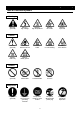
Cautions in Using with Safety Table of Illustrated Symbols Warning Warning, generally Warning, high voltage Warning, high temperature Warning, drive train Warning, explosive Caution, generally Caution, electrical shock Caution, scald Caution, no road heating Caution, not to drench Caution, water only Caution, deadly poison Prohibit, inflammable Prohibit, to disassemble Prohibit, to touch Compulsion, connect to the grounding terminal Compulsion, install on a flat surface Compulsion, discon
Cautions in Using with Safety Fundamental Matters of "WARNING!" and "CAUTION!" WARNING! Do not use this unit in an area where there is flammable or explosive gas Never use this unit in an area where there is flammable or explosive gas. This unit is not explosion-proof. An arc may be generated when the power switch is turned on or off, and fire/explosion may result. (Refer to page 59 "List of Dangerous Substances".
Before Using This Unit Requirements for Installation WARNING! 1. Choose a proper place for installation • Do not install this unit in a place where: ♦ ♦ ♦ ♦ ♦ ♦ ♦ ♦ Rough or dirty surface. Flammable gas or corrosive gas is generated. Ambient temperature above 30°C. Ambient temperature fluctuates violently. There is direct sunlight. There is excessive humidity and dust. There is a constant vibration. Winds from the air conditioner, etc. hit the sample container directly.
Before Using This Unit Requirements for Installation 4. Secure the ventilation of device • Do not operate while the device side/back is obstructed. The temperature inside the device rises and may become the cause of an accident, a failure and a fire. 5. Do not use in the place that the device is exposed to liquid • Do not operate in the place that the device is exposed to liquid. If liquid go inside of the device, it will become the cause of an accident, failure, an electric shock, and a fire. 6.
Before Using This Unit Requirements for Installation CAUTION! 7. Choose a correct power distribution board or receptacle • Choose a correct power distribution board or receptacle that meets the unit’s rated electric capacity. Electric capacity: BB300: 100V AC, 12A BB400: 100V AC, 13A BB600: 100V AC, 20A NOTE) There could be the case that the unit does not run even after turning ON the power.
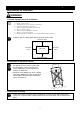
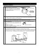
Before Using This Unit Installation Procedure 1 ボタン位置(高) Button position: high Release the stopper lock of the casters. Push down the stopper button of the casters as shown in the right figure. It will be unlocked. (Only the two casters on the front side of the unit are equipped with a caster.) ロック状態(据付) Locked (during installation) ボタン位置(低) Button position: low プッシュでロック解除 Push to unlock the (移動可) caster (movable) キャスター Caster 2 Move the unit to the place of installation.
Before Using This Unit Installation Procedure 6 Precautions about the circulating path • Carefully check the direction of circulation, and connect the hoses properly. Improper connection results in an accident or malfunction of the unit and the circulating path. • Minimize the length of the circulating path. If resistance inside the piping increases, the quantity of circulating fluid decreases, resulting in lower cooling efficiency.
Description and Function of Each Part Main Unit Front view Cover Rating notice sticker Control panel Earth leakage breaker Refrigerator error lamp (Red) (Lights when the refrigerator is overloaded.) Caster (Two front casters have stopper) Condenser filter Refrigerator error lamp (Green) (Lights when the refrigerator is in operation.
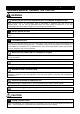
Description and Function of Each Part Control Panel ⑦ ⑫ ⑧ ⑨ ⑩ ⑪ ⑬ ⑭ ④ ① ⑤ ② ③ ⑥ No. Name Function ① RUN/STOP Key: Starts/stops the operation. ② ▲▼ Key: Uses for rising UP/lowering DOWN the setting value. ③ SUB MENU Key: Uses for setting the overheating prevention temperature, calibration offset temperature, or key lock function. ④ ENTER Key: Settles the inputted value. ⑤ FIXED TEMP Key: Chooses the fixed temperature operation.
Description and Function of Each Part Characters of the Controller The characters controller shows are as follows: Character Identifier Name Purpose FiX Fixed Temperature Setting Mode Sv Temperature Setting AStP Auto Stop Setting Used for setting the auto stop operation. AStr Auto Start Setting Used for setting the auto start operation. tim Time Setting End Time-up Used for setting the fixed temperature operation. Used for setting the temperature. Used for setting the time.
Operation Method Operation Mode and Function List The operation modes of this unit are as follows; Name Description Page Fixed Temperature Operation Pressing the FIXED TEMP key enters into the fixed temperature operation setting mode. Pressing it again enters into the temperature setting mode. The " ▲▼" are used to set temperature. Pressing the RUN/STOP key starts or stops operation. 16 Quick Auto Stop Operation This operation is used to specify the period up to automatic stop during operation.
Operation Method Operation Mode and Function List The operation functions of this unit are as follows; Name Overheating prevention function Description Auto overheating prevention function This function is set to be automatically activated (auto reset) when the temperature exceeds the setting temperature by 6℃.
Operation Method Operation Mode, Function Setting Key, and Characters The operation mode setting and function setting use the key operation and characters show in the following figure.
Operation Method Setting of Overheating Prevention Device The unit has the overheating prevention device (manual reset) that consists of independent temperature measurement circuit, CPU, sensor and output circuit (it shares power source, display, and key input with the controller) in addition to the automatic overheating prevention function (auto reset) in the controller. Setting range/function The unit has failsafe functions against overheating.
Operation Method Fixed Temperature Operation In this mode, the unit starts to operate by pressing RUN/STOP key and continues operating at the set temperature until RUN/STOP key is re-pressed, as shown in the figure below. 温度(℃) TEMP SV: Set Temp. SV:温度設定値 SV スタート/ストップkey: キーON RUN/STOP ON Fixed temperature operation procedure スタート/ストップkey: キーOFF RUN/STOP OFF 時間(t) TIME 1.
Operation Method Fixed Temperature Operation 4. Start operation • Press the orange RUN/STOP key for about one second. The unit starts operation and the blinking FIXED TEMP lamp lights on. 5. Stop operation • Press the orange RUN/STOP key for about one second. The unit stops operation and the FIXED TEMP lamp lights off. The screen returns to the initial setting screen. To correct or check setting… Press the FIXED TEMP key again to correct or check the setting.
Operation Method Quick Auto Stop Operation Quick auto stop operation procedure ② This operation is used to specify the period up to automatic stop, i.e., sets the auto stop timer during operation. 1. Set the time up to stop during fixed temperature operation ① Check that the FIXED TEMP lamp lights on and that the unit is under operation. Press the TIMER key. The measurement temperature display screen displays the character "tim", which indicates the timer setting.
Operation Method Auto Stop Operation In this mode, the unit automatically comes to a stop after the set period passes away from the start of fixed-value operation according to timer setting, as shown in the figure below. TEMP 温度(℃) PV SV:温度設定値 SV: Set Temp. PV:温度表示値 PV: Current Temp.
Operation Method Auto Stop Operation 2. Start timer operation • Press the RUN/STOP for one second after deciding the time. • Timer operation starts with the AUTO STOP lamp lighting on. • The timer is activated at the point when the temperature in bath (measurement temperature) reaches to the setting temperature. 3. Stop/terminate timer operation • The operation stops automatically at setting time. • Buzzer continues to sound for about five minutes at operation stop.
Operation Method Auto Start Operation In this mode, the unit automatically starts to operate after the set period passes away from the start of fixed-value operation according to timer setting, as shown in the figure below. However, it does not automatically come to a stop and must be manually deactivated. 温度(℃) TEMP PV SV:温度設定値 SV: Set Temp. PV:温度表示値 PV: Current Temp.
Operation Method Auto Start Operation 2. Start timer operation • Press the RUN/STOP for one second after deciding the time. • Timer operation starts with the AUTO START lamp lighting on. 3. Stop/terminate timer operation • The operation starts automatically at setting time. • Press the RUN/STOP for one second to stop or terminate operation. The screen returns to the timer setting screen.
Operation Method Calibration Offset Function Calibration offset is a function which corrects the difference between the temperature in bath and that of controller (sensor temperature) if arises. The function parallel corrects the difference either to the plus or minus side within the whole temperature range of unit. The function can be set or cancelled by the SUB MENU key. Corrected temp. to plus side Current temperature Corrected temp. to minus side ① Start operation with the target setting temperature.
Operation Method Lock Function This function locks the operation status previously set. SUB MENU key. The function can be set or cancelled by the ① Press the SUB MENU key. Select the character" "Lock", which indicates the lock of setting value, using the "▲▼", and then press the ENTER key. ① ① ① ② The setting temperature screen displays "oFF". The setting value is locked when it is turned to "on" using the "▲". ② ③ Press the SUB MENU key again to cancel the lock.
Operation Method Temperature Output Terminal Precautions • Operate this product according to the procedure described in this Operation Manual. Failure to follow the operation procedure described herein may result in a problem. The guarantee will not apply if you operate the product in the wrong manner. CAUTION! • Turn off the breaker before connecting the cables. • Connect a recorder or another appliance of 600 W or less in input impedance to the temperature output terminal.
Operation Method Temperature Output Terminal Specification • The voltage (DC) corresponding to the measured temperature is output. • Output temperature range: -35 to 85℃ • Output voltage: 4 to 20mA DC Temperature Output (ANALOG) • Load: 600Ω or bellow • Resolution: ±1℃ • Connection: M4 screw terminal block Temperature Output Temp.
Operation Method RS485 Communication Function 1. Settings Relating to Communication 1.1 Communication Settings Before starting communication with the VS3 controller (hereinafter called the "unit"), set communication parameters on the personal computer. Item Communication setting 1 Data length 8 bits 2 Stop bit length 2 bits 3 Parity Disabled 4 BCC check Enabled 5 Baud rate 4800BPS 6 Response delay time 0msec 1.
Operation Method RS485 Communication Function 2. Data Transmission Method Item Specification Communication standard EIA standard, complying with RS-485 Synchronization method Asynchronous communication method Communication method Half-duplex communication Transmission code ASCII code Baud rate 1200/2400/4800/9600BPS Communication distance Max. 500 m (It depends on the effect of the ambient environment.
Operation Method RS485 Communication Function 4.2 Message Types ■ Message types include transmission request messages from the host computer and transmission reply messages from this unit. ■ All codes from STY, address, request, identifier to ETX (except BCC) are represented by ASCII codes. 4.3 Request Message Structures (transmission from the host computer to the unit) 4.3.
Operation Method RS485 Communication Function 4.4 Reply Message Structures 4.4.1 Reply Messages to Read Request Messages ① ② ④ ⑤ ⑥ ⑦ ⑧ Start code Address Identifier Numeric data End code BCC data Acknowledgement code S T □ □ X A C □ □ □ □ □ □ □ □ K E T X B C C ① ⑧ ⑥ ⑦ ② ④ ⑤ 4.4.2 Reply Messages to Write Request/Storage Request Messages ① ② ⑥ ⑦ ⑧ Start code Address End code BCC data Acknowledgement code S T □ □ X A C K ① ⑧ ⑥ ② E T X B C C ⑦ 4.4.
Operation Method RS485 Communication Function 4.5 Description of Codes ■ The following codes from ①STX, ②address to ⑩error type are represented by ASCII codes. ■ For ASCII codes, see "8. List of ASCII Codes." ■ For conversion into ASCII codes, see "5. Communication Examples." ① STX This code is required for the receiving side to detect the head of a message. Add it at the head of the character string to be transmitted. ② Address This is the address of the unit with which the host computer communicates.
Operation Method RS485 Communication Function ⑨ NAK This is a negative acknowledgement code and included and returned in the "reply message" from the unit when there is an error in the "request message" received by the unit. ⑩ ERR type If there is an error in the "request message" received by the unit, this code is included in the "reply message" from the unit after "(9) NAK" to report the type of the error. This is a communication-related error, and details of display are omitted.
Operation Method RS485 Communication Function 5. Communication Examples 5.1 Read communication example Example) Request message: A request for reading PV is transmitted to the unit set at address 02. Reply message from the unit to this request message: The data of PV (00123) is returned.
Operation Method RS485 Communication Function 5.2 Write communication example Example) Request message: A request for setting "SV to 135" (writing 135) is transmitted to the unit set at address 03. Reply message from the unit to this request message: Information that the request message has been received is returned. ・Confirm that the data has been properly written by reading it separately.
Operation Method RS485 Communication Function 6. Wire Connection Shown below is an example of multi-drop wire connection. VS3 Built-in Device AC adapter ID:01 Cable 2 CN3-3,4 KS-485 RS232C/485 converter VS3 controller PC Cable 1 ID:02 Cable 3 CN3-3,4 VS3 controller Up to 31 stations can be connected.
Operation Method RS485 Communication Function 7. List of Identifiers/Commands *1: "_" means a space. *2: The setting range depends on other parameters. (See the table shown below.) *3: A parameter with which a W command is valid during each operation (valid during operation in regular mode).
Operation Method RS485 Communication Function Other Parameters Name Identifier Command LOC R/W RUN R/W RST R/W _TI R Output monitor OM1 R Error monitor 1 ER1 R Error monitor 2 ER2 R Measured temperature monitor PV1 R Key lock Operation start/stop Operation selection type Remaining hour monitor Setting Value 00000:Key lock released 00001:Key lock 00000:Stop (*3) 00001:Start 00000:Fixed temperature operation selected (*3) 00000:Time-up (*1) 00001~09950:0 hours and a minute to 999 hou
Operation Method RS485 Communication Function 8.
Operation Method Cooling curve, cooling capacity curve (reference data) The graphs show the cooling and cooling capacity curves of each model below. Use the values just for reference because they depend on the sample volume, the ambient temperature, etc.
Operation Method Cooling curve, cooling capacity curve (reference data) BB600 heating and cooling curves BB600加熱冷却曲線 100 室温 temperature: :20℃20°C Room 使用ブライン :水道水(上昇) (rising curve) 90 Fluid: Tap waterエチレングリコール50%(下降) Ethylene glycol 50% (downward curve) 液量 measure::26L (自槽満水) Fluid 26L (full capacity) 80 電源 :AC100V 50Hz Power supply: 100V AC 50Hz 60 50 40 30 20 10 0 -10 -20 -30 -40 0 10 20 30 40 50 60 70 80 90 100 Elapsed 経過時間(分) time (minutes) BB冷却能力曲線 BL cooling capacity curves 1100 1000
Operation Method Flow Rate and Head (reference data) Lift (m) 楊程(m) BB流量楊程 BB flux and lift 1.5 1.4 1.3 1.2 1.1 1 0.9 0.8 0.7 0.6 0.5 0.4 0.3 0.2 0.1 0 60Hz 50Hz 0 0.5 1 1.5 2 Flux (L/min) 流量(L/min) 41 2.5 3 3.
Operation Method Nybrine Freezing Temperature and Viscosity (reference data) ナイブラインZ 1,Zof 1-KおよびナイブラインNFPの凍結温度 Freezing temperatures Nybrine Z1, Z1-K, and Nybrine NFP 0 0 -10 ナイブラインNFP Nybrine NFP -20 -20 Nybrine Z1,1,Z Z1-K ナイブラインZ 1 -K -30 -30 -40 -40 -50 -50 0 10 20 30 40 50 60 70 80 90 100 Nybrine concentration (wt%) ナイブライン濃度(wt%) Viscosity ofナイブラインZ Nybrine Z1, 1 ,Z Z1-K, 1-K,RH水溶液の粘度 and RH aqueous solution) 1000 800 600 400 200 Freezing 凍結 Kinetic viscosity = Viscosity/
Operation Method Device to Install (reference data) Bath capacity of this unit is BB100 type: 6, BB300 type: 13, BB600 type: 26. Be careful that it may leak outside if the quantity is beyond the capacity. Kinds and quantity of Erlenmeyer flask to be set in the bath is as follows.
Handling Precautions WARNING! If a problem occurs If smoke or strange odor should come out of this unit for some reason, turn off the power key right away, and then turn off the circuit breaker and the main power. Immediately contact a service technician for inspection. If this procedure is not followed, fire or electrical shock may result. Never perform repair work yourself, since it is dangerous and not recommended.
Handling Precautions CAUTION! Do not step on this unit Do not step on this unit. It will cause injury if this unit fall down or break. Do not place or drop anything on the unit Do not place or drop anything on the unit. Since the unit contains precision components, it may malfunction due to vibration, impact, etc. During a thunder storm During a thunderstorm, turn off the power key immediately, then turn off the circuit breaker and the main power.
Handling Precautions Recovery from a power failure If the unit was deactivated in the middle of operation due to a power failure and is re-energized, the unit automatically returns to the state just before the power failure and resumes operation. If the resumption of operation by automatic recovery is inconvenient, turn off the leakage breaker.
Maintenance Method Daily Inspection and Maintenance For the safety use of this unit, please perform the daily inspection and maintenance without fail. Using the city water to this unit might attach dirt. Do inspect and maintain this point while performing daily inspection and maintenance. WARNING! • Disconnect the power cable from the power source when doing an inspection or maintenance unless needed.
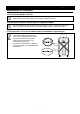
Maintenance Method Daily Inspection and Maintenance Cleaning the filter A clogged filter deteriorates cooling performance or causes the refrigerator to malfunction. The clogged state depends on the ambient environment or working period. Clean the filter at regular intervals according to the working conditions. The mesh plate is fixed with a magnet. Pull it toward you. The bottom of the mesh plate is slipped over pins. Lift it up and remove it. The filter cover is fixed with a magnet.
Long storage and disposal When not using this unit for long term / When disposing CAUTION! When not using this unit for long term… • Turn off the power and disconnect the power cord. WARNING! When disposing… • Keep out of reach of children. • Remove the driving parts. • The unit uses a CFCs substitute. Ask a qualified disposal service company for the disposal of it.
In the Event of Failure… Safety Device and Error Code This unit has an automatic diagnosis function built in the controller and safety devices independent of the controller. The table below shows the cause and the solution method when the safety device operates. Error Code: When an abnormal condition occurs, an error code appears and the alarm lamp lights in the controller, the buzzer sounds simultaneously. Record the error code and turn off the power of device immediately.
In the Event of Failure… Trouble Shooting Phenomenon Check point The unit does not start to operate • Check if the power cable is securely connected to the power although the leakage breaker is supply. turned on. • Check if the power fails. "ALARM” lamp lights on. • Check the error code on page 46. The temperature does not drop. • Check if the set temperature is higher than the inside temperature of the bath. • Check if the condenser filter is dirty. • Check if the condenser fin is contaminated.
After Service and Warranty In Case of Request for Repair If the failure occurs, stop the operation, turn OFF the power switch, and unplug the power plug. Please contact the sales agency that this unit was purchased, or the Yamato Scientific's sales office. < Check following items before contact > ◆ ◆ ◆ ◆ Model Name of Product See the production plate attached to this unit.
Specification Product Name Model Low constant temperature water bath BB300 BB400 Circulation unit Performance Usable ambient temp. Temperature control range Temperature adjustment accuracy Temperature distribution accuracy Cooling capacity External sealed unit circulation 5℃~30℃ -30℃~80℃ ±0.1℃ ±0.3℃ Approx.420W at15℃ Approx.510W at15℃ Stirring method Configurations 1.1/1.
Wiring Diagram BB300 ELB T1 1 ・ 2 CN5 ・ 3 1 AC100V 2 2 1 X2 H 3 SSR 3 4 1 2 CN2 3 4 X1 X3 M 5 X2 C3 L2 6 18 18 1 1 18 18 1 CN1 CN9 1 CN1 2 CT1 1 CN8 CN2 PIO 1 1 ・ 2 ・ 3 ・ CN4 4 ・ 5 ・ 6 ・ 3 TB2 PS 1 2 7 FM K - X4 X3 1 2 CN3 3 4 8 X1 T2 + 1 CN6 2 FS X4 Pt TB1 2 T3 1 2 3 4 + Temperature output 温度出力(4-20mA) - (4-20mA) A+ RS485 communication RS485通信 A- PLB 1 C1 C2 OVR 3 2 X5 L1 1 X5 3 C RF Symbol ELB T1 T2 T3 H SSR CT PLB PIO Pt K FM RF OVR S
Wiring Diagram BB400 ELB T1 1 ・ 2 CN5 ・ 3 1 AC100V 2 2 1 X2 H 3 SSR 3 4 1 2 CN2 3 4 X1 X3 M 5 X2 C3 L2 6 18 18 1 1 18 18 1 CN1 CN9 1 CN1 2 CT1 1 CN8 CN2 PIO 1 1 ・ 2 ・ 3 ・ CN4 4 ・ 5 ・ 6 ・ 3 TB2 PS 1 2 7 FM K - X4 X3 1 2 CN3 3 4 8 X1 T2 + 1 CN6 2 FS X4 Pt TB1 2 T3 1 2 3 4 + Temperature output 温度出力(4-20mA) - (4-20mA) A+ RS485通信 RS485 communication A- PLB 1 C1 C2 OVR 2 3 X5 L1 1 X5 3 C RF Symbol ELB T1 T2 T3 H SSR CT PLB PIO Pt K FM RF OVR S
Wiring Diagram BB600 ELB T1 1 ・ 2 CN5 ・ 3 1 AC100V 2 2 1 X2 H 3 SSR 3 4 4 M 1 2 CN2 3 X3 X1 C3 5 X2 L2 6 18 18 1 1 18 18 1 CN1 CN9 1 CN1 2 CT1 1 CN8 CN2 PIO 1 1 ・ 2 ・ 3 ・ CN4 4 ・ 5 ・ 6 ・ 3 TB2 PS 1 2 K - T3 1 + Temperature output 温度出力(4-20mA) 2 - (4-20mA) 1 FS X4 X3 1 2 CN3 3 4 8 X1 T2 + CN6 2 7 X4 Pt TB1 2 3 A+ RS485 communication RS485通信 4 A- PLB 1 FM OVR C1 C2 2 X5 X5 L1 3 C S RF R Symbol ELB T1 T2 T3 H SSR CT PLB PIO Pt K FM RF OVR 4 Pa
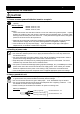
Piping Diagram Return port (IN) External circulation switching cock Stirring motor Overflow Discharge port (OUT) External device (sealing system) Internal stirring Stirring fan Main unit Drain cock 57
Replacement Parts Table Common parts for all models Symbol Part Name Code No.
Reference List of Dangerous Substances Never use explosive substances, flammable substances and substances that include explosive or flammable ingredients in this unit.
Installation Standard Manual * Install the unit according the procedure described below (check options and special specifications separately). Model № Serial number Date Item Person in charge of installation (company name) Method Person in charge of installation Reference operation manual Specifications 1 2 Accessories Installation Check the quantities of accessories with the quantities shown in the Accessory Specification column. P.53 ・Visually check the surrounding area.
Responsibility Please follow the instructions in this document when using this unit. Yamato Scientific has no responsibility for the accidents or breakdown of device if it is used with a failure to comply. Never conduct what this document forbids. Unexpected accidents or breakdown may result in. Note ◆ The contents of this document may be changed in future without notice. ◆ Any books with missing pages or disorderly binding may be replaced.