
Information

SPECIFICATIONS AND DRAWINGS ARE SUBJECT TO ALTERATION WITHOUT PRIOR NOTICE - DIMENSIONS IN MILLIMETER
45
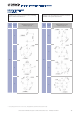
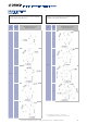
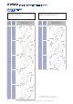
ASSEMBLY INSTRUCTIONS
MONTAGEANLEITUNG
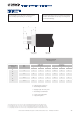
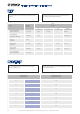
Size
Größe
09 12 15 18
Nm
Nm
0.6 1.0 2.0 4.0
TECHNICAL INFORMATION / TECHNISCHE ANGABEN
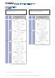
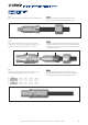
Step 5
Insert insulator with half shells and collet in the housing. Make
sure that the nose of the of the collet (3) is aligned with the colour
marking (1) and the grove at the thread (2) of the enclosure.
Step 6
Push the back nut forward and use spanner to close the connector.
Use the following tightening torques to fix the back nut:
Schritt 5
Schieben Sie den Isolator mit den Halbschalen und der Spannzange in
das Gehäuse. Vergewissern Sie sich, dass die Nase der Spannzange (3)
sich in einer Linie mit der Farbmarkierung (1) und der Nut am Gewinde
des Gehäuses (2) befindet.
Schritt 6
Drücken Sie die Spannmutter nach vorne und nutzen Sie einen
Gabelschlüssel, um den Steckverbinder zu schließen. Verwenden Sie
die folgenden Anzugsmomente, um die Spannmutter zu fixieren:
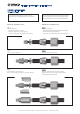
Step 4
Push collet forward and clamp shielding between collet and half shells.
Schritt 4
Schieben Sie die Spannzange nach vorne und klemmen Sie die
Abschirmung zwischen die Spannzange und die Halbschalen.
1 2 3