
User Manual
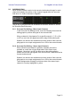
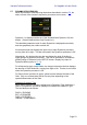
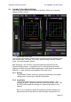
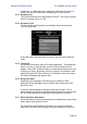
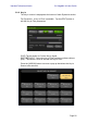
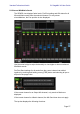
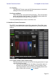
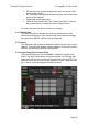
Table Of Contents
- 1.0 System Requirements
- 2.0 Wi-Fi Settings
- 3.0 Getting Started
- 4.0 Mixer Window
- 4.1 Channel Bank Navigation
- 4.2 Layer Navigation
- 4.3 Channel Names and Colors
- 4.4 Faders
- 4.5 Channel ON
- 4.6 CUE
- 4.7 Dual Cue Mode
- 4.8 SOLO Mode
- 4.9 Master Bank
- 4.10 GAIN
- 4.10.1 Digital Gain
- 4.10.2 Gain Compensation Mode
- 4.10.3 Analog Gain / Digital Gain Link
- 4.10.4 ALL GC ON
- 4.10.5 ALL GC OFF
- 4.10.6 Input Port
- 4.10.7 Phantom Power
- 4.10.8 Phase
- 4.10.9 Dante Wireless Microphone Control and Monitoring
- 4.10.10 Non-Dante Wireless Microphone Control and Monitoring
- 4.10.11 Input Port Patching
- 4.10.12 Input Port Patch Options
- 4.10.13 Multi-Channel Input Patching
- 4.11 SENDS ON FADERS
- 4.12 DCA GROUP MASTER FADERS
- 4.13 DCA GROUP ASSIGNMENT
- 5.0 EQ / PAN / 5.1 / DYNAMICS/ SENDS
- 6.0 OUTPORTS
- 7.0 UTILITY
- 8.0 RACK
- 8.1 GEQ Racks
- 8.2 EFFECT Rack
- 8.3 EFFECT EDITING
- 8.3.1 Current Effect
- 8.3.2 Effect Type Selection
- 8.3.3 Effect Library
- 8.3.4 Input and Output Patch Assignments
- 8.3.5 Input and Output Meters
- 8.3.6 Effect Bypass
- 8.3.7 Effect Cue
- 8.3.8 Close Effect Editor
- 8.3.9 Parameter Editing using Sliders
- 8.3.10 Numerical Parameter Editing
- 8.3.11 Multi-Segment Buttons
- 8.3.12 Accessing Parameters
- 8.3.13 Additional Parameters
- 8.3.14 Wet/Dry Mix
- 8.4 GRAPHICAL EFFECT EDITING
- 8.4.1 REV-X Time/Level Parameters
- 8.4.2 REV-X Space Parameters
- 8.4.3 REV-X Filter Parameters
- 8.4.4 REVERB Time/Level Parameters
- 8.4.5 REVERB Space Parameters
- 8.4.6 REVERB Filter Parameters
- 8.4.7 REVERB Dynamics Parameters
- 8.4.8 STEREO REVERB Program
- 8.4.9 MONO/STEREO/MOD DELAY Parameters
- 8.4.10 DELAY LCR Parameters
- 8.4.11 ECHO Parameters
- 9.0 SCENE MEMORY
- 10.0 SETUP
- 10.1 Fader Delay
- 10.2 Filled EQ Graph
- 10.3 Enable Inc/Dec Scene Recall
- 10.4 Show Send Levels in Meter Bridge
- 10.5 Enable Phantom Power Switching
- 10.6 Set EQ band to 0dB with Double-Tap
- 10.7 Show dB Markings on Mixer
- 10.8 Set DCA to 0dB with Double-Tap
- 10.9 Disable Screen Auto-Lock
- 10.10 Cue Operation Mode
- 10.11 Cue A Mode
- 10.12 Cue B Mode
- 10.13 Solo in Place Mode
- 10.14 Channel Select – StageMix Follows Console
- 10.15 Channel Select – Console Follows StageMix
- 10.16 Input Meter Point
- 10.17 Output Meter Point
- 10.18 Display Key Input for Dynamics Meters
- 10.19 RTA Peak Hold Mode
- 10.20 RTA Input Gain
- 10.21 RTA Number of Bands
- 11.0 Troubleshooting

Yamaha Professional Audio CL StageMix V8 User Guide
Page 59
• RF Receiver Gain (purple background), fader only shown when
active for the channel.
• RF Transmitter Gain (purple background) fader only shown when
active for the channel.
• Digital Gain (blue background)
• Channel Direct Output level, ON, Position and Patch. Touch on
the position button to change the Direct Output position.
For output channels, the above controls do not apply.
5.10.2 Recall Safe
The [ON] will enable or disable the recall safe master status of the
current selected channel. If the channel recall safe parameter settings
are partial, the PARTIAL indication will be displayed.
5.10.3 Insert
The [ON] button will enabled or disable the Insert Return for the current
channel. The insert send position can be edited by touching the position
indicator and selecting a different send position.
5.10.4 Input Delay (input Channel Only)
The Input Delay function can be enabled or disabled using the [ON]
button. The delay value can be set by touching the time indicator, and
entering the desired value in the pop-up editor and touching [SET]. The
up/down arrows can be used for fine adjustment. Once a time has been
set, it can be copied and pasted to another channel.