OPERATION, SERVICE & PARTS MANUAL Before installing hoist, fill in the information below. Refer to the Hoist and Motor data plates. Model No. _________________ Serial No. _________________ SERIES Y80 Purchase Date _____________ Voltage ___________________ ® YALE Rated Load _______________ WIRE ROPE ELECTRIC HOISTS INCLUDING WEIGHT WATCHER OVERLOAD CLUTCH MODELS RATED LOADS 1/2 THRU 5 TONS Printed in U.S.A.
FOREWORD This manual contains important information to help you install, operate, maintain and service your new YALE electric hoist. We recommend that you study its contents thoroughly before putting the hoist into use. Read ANSI B30.16 safety code for hoists. Then, thru proper installation, application of correct operating procedures and by practicing the recommended maintenance suggestions you can expect maximum lifting service from the hoist.
SECTION I — GENERAL DESCRIPTION 1-1. GENERAL. YALE electric hoists are precision built wire rope and drum type hoists which are made in five rated load sizes (1/2, 1, 2, 3 and 5 tons) with various lifts, lifting speeds and electrical service. Equipped with an integrally welded mounting lug, they are designed to be rigidly attached to an overhead structure or mounted on YALE rigid mount trolleys for operation on runway beams.
For trolleys which are to be mounted along the span of a beam not having open ends, measure exact width of beam flange and assemble trolley to hoist so that spacing between wheel flanges is 1/4" (see Figure 2-1) greater than beam width (3/8" if beam has curves). This is accomplished by rearranging the spacer washers on the bolts connecting trolley side plates to hoist mounting lug. If trolley is shipped separate from hoist, see instruction sheets furnished with trolley for orientation and installation.
b. Check Push Button Operation and Phasing. WARNING On three phase hoists it is possible to have “Reverse Phasing” causing the lower block to lower when the á button is depressed. When this condition exists, the automatic limit stop switch is inoperative and hoist operation will be dangerous. When floating rod is raised, stop switch is actuated first and then the reversing switch is actuated (Figure 2-3). Stop switch stops hoist. Reversing switch lowers hook block in case of floating rod over-travel.
SECTION III — OPERATION 3-1. GENERAL. Operation of Series 800 YALE electric hoists is controlled by a convenient pendant push button station. With it, the hoist can be controlled to give fast lifting and lowering; or controlled to lift or lower load in small increments, providing accurate spotting. The push button station has a built-in interlock to prevent depressing opposing buttons simultaneously.
SECTION IV — LUBRICATION ak. DO NOT adjust or repair a hoist unless qualified to perform hoist maintenance. al. DO NOT attempt to lengthen the wire rope or repair damaged wire rope. am. DO NOT allow personnel not physically fit or properly qualified to operate hoist. an. DO NOT operate hoist unless limit switch is operating properly. ao. DO be sure there is no twist in wire rope. ap. DO avoid operating hoist when hook is not centered under hoist.
4-6. LUBRICATE LIMIT SWITCH. Provide a light film of NLGI No. 2 grease on bevel gear of limit switch. SECTION V INSPECTION AND PREVENTIVE MAINTENANCE 5-1. GENERAL. YALE, Series 800, hoists are inspected and tested at the factory. Regular in service inspection and preventive maintenance programs not only help reduce overall maintenance costs but may also prevent serious shutdowns by forewarning of problems that could cause these shutdowns.
5-2. INSPECT LOWER BLOCK. a. Check lubrication of all parts. If the thrust bearing is not equipped with a grease fitting, lubricate with SAE No. 50 oil. Also lubricate the shank of the hook which passes through the lower block body. b. Check each sheave to ensure rope groove is smooth and free from burrs, or other surface defects. c. Check each sheave for freedom of rotation; replace bearings if defective. d. Make certain that dowel pin, holding the hook nut to the hook, is securely in position. e.
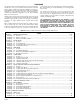
INSPECTION SCHEDULE AND MAINTENANCE REPORT HOIST SERIAL NO. (MFGRS) _______________________ RATED LOAD _________________ TYPE ________________________ VOLTAGE _____________________ CLEANING OR PAINTING REQUIRED LUBRICATION REQUIRED (Low Oil or Grease, Rust or Corrosion) REPLACEMENT REQUIRED (Worn or Damaged) REPAIR REQUIRED (Loose Parts or Wires) CONDITION (Check column best indicating condition when part or unit is inspected. Use note column to the right if condition is not listed below.
TIME INTERVAL Daily or start of each shift (\/isual) INSPECTION OR MAINTENANCE Check operation of all functional mechanisms including limit switch operation, brakes and control. Check hoist cable for kinks, abrasions, corrosion or broken wires or evidence of improper spooling on drum. Inspect hooks, upper and lower blocks, and all load bearing components for damage. 1 Month * HOIST CABLE — Inspect and lubricate per paragraph 5-8. 1 - 3 Months * ELECTRICAL CONTROLS — Inspect per paragraph 5-4.
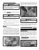
(2) Using a puller tool, remove brake flange from shaft. A groove is provided around outer diameter for this purpose. See Figure 5-7. Remove key from shaft and lift off 2 friction discs, and the pawl and ratchet assembly (Figure 5-8). 11421 Figure 5-4. Removing Intermediate Gear and Pinion Assembly. 10334 Figure 5-7. View Showing Load Brake Flange Removed. (3) Remove load brake gear. If replacement of spring, spring retainer or cam is necessary, press off shaft (Figure 5-9).
(1) Before installing spring in its retainer (Figure 5-9), apply a good grade of ball bearing grease to inside of retainer. Spring must be positioned exactly as illustrated, butted against pin at side of cam. LOAD BRAKE — OVERLOAD CLUTCH (4) The brake spring must be pre-loaded at assembly to a torque of from 10 to 14 lb.-ft. This is accomplished using a plumber’s strap wrench to wind (rotate) load brake gear to set up spring (Figure 5-10) while pressing brake flange into place using an arbor press.
b. Maintenance. Keep rope well lubricated to help reduce internal friction and prevent corrosion. Lubricant, as described in paragraph 4-3, should be applied as a part of the regular maintenance program. Special attention is required to lubricate sections of rope over equalizing sheaves and other hidden areas. Avoid dragging ropes in dirt or around sharp objects which will scrape, nick, crush or induce sharp bends in the rope. c. Replacement.
(5) Remove key plates or snap rings from upper block sheave(s) and slide out upper block sheave pins, releasing upper block sheaves. Remove wire rope from sheaves. With new rope installed on the drum as described in paragraph 5-9c single reeved above, proceed with rereeving following steps below: (6) Make certain all personnel are clear of hoist and operate hoist â to completely unwind all wire rope from drum. Stop hoist so drum anchor slot(s) is accessible. Remove live rope and socket(s) from drum.
(1) Grasp cable at a point one-third (approx. 14’0") the distance hanging below the rope drum and form a loop. Place one upper sheave in this loop. Slide upper sheave with cable into sheave pocket; partially insert sheave pin to hold sheave in place. (2) Repeat (1) above and install second upper sheave with rope. Insert sheave pin and install key plates and bolts to secure sheave pin. Figure 5-13. Upper Sheave Installed.
(d) Tur n on power ; raise and lower the block several times to feed the correcting twist in the rope through the reeving. (e) If block still tends to twist, repeat the above procedure until block rotation is corrected. (2) To remove rope twist in double reeved hoists. (a) Observe direction block tends to rotate. (b) Lower the bottom block unspooling rope from rope drum until only one quarter (1/4) turn remains to rope end anchors in drum. Figure 5-16. Upper Sheave Installed (Typical).
WARNING BEFORE ATTEMPTING TO TEST THE OVERLOAD CLUTCH, MAKE CERTAIN THE FOLLOWING PREREQUISITES ARE STRICTLY OBSERVED: a. An appointed person must determine, before starting, that all structures supporting the hoist are adequately strong to withstand the test load of 200% of the rated load, plus the weight of the hoist, whether hoist is tested in installed position or moved to a designated test facility. b. Loads used for testing must be accurately known. c.
SECTION Vl - TROUBLE SHOOTING Trouble 6-1. Hoist Will Not Operate. 6-2. Hook Moves in Wrong Direction. 6-3. Hook Will Raise But Not Lower. 6-4. Hook Will Lower But Not Raise. Probable Cause Remedy a. No power to hoist. a. Check switches, circuit breakers or fuses and connections in power supply lines. Check power collectors. b. Wrong voltage. b. Check voltage required on motor data plate against power supply. c. Loose or broken wire connections in hoist electrical system. c.
SECTION Vl - TROUBLE SHOOTING (Continued) Trouble 6-5. Hoist Will Not Lift Rated Load. Probable Cause a. Low voltage Remedy a. See that power supply current is same voltage Iisted on motor data plate. Check hoist motor connections. Check size of power supply lines. b. Overload Clutch not properly b. See Section VII, paragraph 7-5. adjusted. 6-6. Hoist Motor Overheats. a. Excessive load. a. Reduce loading to rated load of hoist, shown on nameplate. b. Excessive duty-cycle. b.
SECTION Vll — ADJUSTMENTS 7-1. MECHANICAL LOAD BRAKE. The mechanical load brake on Series 800 YALE hoists is a pawl and ratchet “Weston” type automatic brake. The brake is not adjustable and requires only periodic inspection and occasional replacement of the friction washers. 7-2. MOTOR BRAKE. Instructions for adjusting the brake are inside the brake cover and are repeated below. Check brake adjustment after the first 30 days of service and regularly thereafter during the six-month inspection procedure.
c. Turn proper adjustment disc (right for up, left for down) toward stitch to reduce hook travel or away from switch to increase hook travel. hoist is furnished as a separate insert and shipped with hoist. We suggest you carefully file the wiring diagram with this book for future reference. d. Slide locking plate back into position ensuring slots on adjustment discs are fully engaged, tighten locking plate screws to 4 in-lbs.
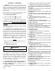
11455C Figure 9-1. Frame, Gearcase and External Parts. Ref. No. Part Number 1 2 3 4† 5 6 800-197 800-192 800-105 800-106 800-107 800-109 800-111 800-2100 800-108 800-110 800-2101 7 800-113 800-115 800-112 800-114 800-2102 800-2103 800-2104 800-2105 Description Plug — Oil Level Cover & Bearing Assembly — Gearcase Dowel Gasket — Gearcase Gearcase & Bearing Assembly Drum & Hub Assembly (Double Reeved Models) 1/2 & 1 Ton (3/6" Dia. Rope) 18' Lift 34' Lift 47' Lift 2 Ton (1/4" Dia.
Figure 9-1. Frame, Gearcase & External Parts. (Cont’d.) Ref. No. 8 9 Part Number 800-116 800-117 800-118 800-2106 800-2107 800-2108 800-2109 9A 12 14 15 19 20 21 22† 23 24 25 26 27 29 30 32 34 35 41 43 44 45† 800-2110 800-2111 800-2112 800-121 800-124 800-125 800-130 800-131 800-2113 800-2114 800-132 800-133 800-134 800-135 800-136 800-137a 800-138 800-139 800-194c 800-2121 800-146a 800-2122 800-149 See Fig. 9-3 & Fig.
Figure 9-1. Frame, Gearcase & External Parts. (Cont’d.) Ref. No.
11456LC Figure 9-2. Gearing and Load Brake Parts. Ref. No.
Figure 9-2. Gearing and Load Brake Parts. (Cont’d.) Ref. No.
12756H Figure 9-3. Hoist Motor Brake - Later Version. Ref. No. 1 2 3 4 5 6 7 8 9 10 11 14 15 16 17 18 19 20 21 22 23 24 25 26 27 28 29 30 31 Part Number 800-2401 * 800-2402 * * * * * 800-2410† * * 800-2411 * 800-2403 * * * * * * * * * * 800-2404 * * * Description Motor Brake Assembly (Includes Ref. Nos.
Figure 9-3. Hoist Motor Brake. (Cont’d.
12756A Figure 9-4. Hoist Motor Brake - Early Version. Ref. No. Part Number 1 2 3 4 5 6 7 8 9 10 11 14 15 16 17 18 20 21 22 23 24 25 26 27 28 29 30 31 32 800-1400 800-1401 * 800-1402 * * * * * * * * * * 800-1403 * * 800-1404 * * * * * * * * * * * 800-1405 * Description Motor Brake Assembly (Includes Ref. Nos.
Figure 9-4. Hoist Motor Brake. (Cont’d.
12724 Figure 9-5. Three Phase Motor Assembly. Ref. No. Part Number 800-1301 800-1302 800-1303 800-1304 800-1305 800-1306 800-1307 800-1308 800-1309 800-1310 800-1311 800-1312 800-1313 800-1314 800-1315 800-1316 800-1317 800-1318 800-1319 800-1320 800-1321 1 2 3 4 5 6 7 8 800-1322 800-1323 800-1324 800-1325 * * * * * * * * Description Motor Assembly (Includes Ref. Nos.
11460 Figure 9-6. Upper Limit Switch Parts. Ref. No.
12748A Figure 9-7. Electrical Control Equipment. Ref. No. Part Number Description 3 5 6† 7† 8 9† 10 11† 12 800-670 800-654 800-655 800-656 800-657 800-671 800-663 800-672 800-673 800-674 800-675 800-676 Cord Grip — Conductor Screw — Self-Tapping Contactor — Two Speed Contactor Screw — Self-Tapping Transformer Screw — Self-Tapping Terminal Board (Reconnectable Hoist Only) Fuse, Fuse Holder and Wire Assembly Fuse Only (2A, 300V) Brake Module Screw — Self Tapping 13 14 † Recommended Spares.
12763 Figure 9-8. Push Button Station and Conductor Cable Assembly. Single Speed Hoists. Ref. No. Part Number 800-2701 1 2 3 4 5 6 7 8 9 10 11 12 13 14 15 16 17 800-2702 * * * 800-2703 * 800-2704 800-2705 * * * * * * 800-2706 * 800-2707 800-2708 Description Push Button Station and Conductor Cable Assembly (Includes Ref. Nos. 1 thru 17) Push Button Station (Includes Ref. Nos. 1 thru 15) Type 1 Pan Head Machine Screw (M 3.5 x 0.6 x 12 Pltd.) Lockwasher (M 3.5 Pltd.
12721A Figure 9-9. Push Button Station and Conductor Cable Assembly. Two Speed Hoists Only - Later Version. Ref. No. Part Number 800-1821 1 7 11 12 13 14 15 16 17 18 19 Page 36 800-1822 800-1823 800-1812 800-1813 800-1814 * * * * * * * Description Push Button Station and Conductor Cable Assembly (Includes Ref. Nos. 1 thru 30) Grommet Conductor Cable Operator Warning Label Push Button Station (Includes Ref. Nos.
Figure 9-9. Push Button Station and Conductor Cable Assembly. (Cont’d.) Ref. No. Part Number 20 21 * * 800-1815 800-1816 * 800-1817 22 800-1818 23 24 25 26 27 28 29 30 ** * ** ** ** ** ** ** Description Clamp — Conductor Contact Block Assembly Contact Block (ZB2-BE101) Contact Block (ZB2-BE201) Interlock—Mechanical Up Push Button Assembly (Includes 1 Each of Ref. Nos. 23 and 25 thru 29) Down Push Button Assembly (Includes 1 Each of Ref. Nos.
12721 Figure 9-10. Push Button Station and Conductor Cable Assembly. Two Speed Hoists Only - Early Version. Ref. No. Part Number 800-1801 1 2 3 4 5 6 7 8 9 10 11 12 Page 38 800-1802 800-1803 800-1804 800-1805 800 1806 800-1807 800-1808 800-1809 800-1810 800-1811 800-1812 800-1813 800-1814 Description Push Button Station and Conductor Cable Assembly (Includes Ref. Nos.
Figure 9-10. Push Button Station and Conductor Cable Assembly. (Cont’d.) Ref. No.
11464 Figure 9-11. Lower Block Assembly — Two Parts Rope, Single Reeved. Ref. No. 1 2 3 4 5 6 † 7 8 † 7 8 9 10 † † 11 12 † † 13 14 15 Part Number 800-801 800-802 800-803 800-804 800-805 800-806 800-807 800-808 800-809 800-810 800-811 800-812 800-813 800-814 800-815 800-816 800-817 800-818 800-819 800-820 800-821 800-822 800-823 800-824 800-825 800-826 800-827 800-828 800-829 800-830 800-831 800-832 800-833 800-834 † Recommended Spares.
11465 Figure 9-12. Lower Block Assembly—Two Parts Double Reeved. Ref. No.
12197LA Figure 9-13. Upper and Lower Block Parts (3 & 5 Ton — Typical). Ref. No.
12757A Figure 9-14. Screw-Type Limit Switch Parts. Ref. No. Part Number 1 2 3 4 800-1655 800-1651 800-1652 800-1657 Description Limit Switch Assembly (Includes Ref. Nos. 2, 3 and 4) Cap Screw — Hex Socket Head Sealing Washer Drum Shaft Insert Qty. Req’d. 1 3 3 1 For switch element replacement order 800-1654.
Recommended Spare Parts for Your Yale Hoist Certain parts of your hoist will, in time, require replacement under normal wear conditions. It is suggested that the following parts be purchased for your hoist as spares for future use.