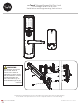
nexTouch™ Keypad Access Exit Trim Lock Touchscreen and Push Button Installation and Programming Instructions WARNING This product can expose you to lead which is known to the state of California to cause cancer and birth defects or other reproductiveharm.For more information go to www.P65warnings.ca.gov. 08/2018 Retrofitting or modifying this product may impact fire rating, safety features and warranty. Consult with code specifications to ensure compliance with all codes and ratings.
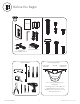
AA AA template AA AA Before You Begin Fire Guard Optional Privacy DPS Switch Optional Network Module Tools Needed Outswinging Door Left Hand Reverse Interior Right Hand Reverse Exterior #3 & #2 Face a door swinging open toward you. If it swings open to the right, it is a right hand reverse door. If it swings opens to the left, it is a left hand reverse door.
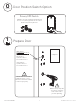
O optional Door Position Switch Option Privacy DPS Switch With Door Position Switch installed and door closed, all keypad functions can be disabled by Privacy Button. 1 Prepare Door DPS Option for Privacy Function template Wood Door: 3/8" Dia. Thru to Hole in Door Face *Metal Door: 3/4" Dia. Thru to Hole in Door Face *Metal Door Installations Supplied plastic collar MUST be installed for DPS to function properly. Drill holes 1/2 way thru door then complete from other side to prevent splitting.
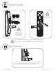
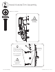
2 Install Cylinder Tighten counter-clockwise to secure lock. X Use key to thread cylinder. Pull key out of cylinder to first blade cut for best operation. If using cylinder other than 1-1/8", a new collar must be used that is sized appropriately for cylinder length. Test Cylinder Test cylinder by turning key counter-clockwise to unlock trim. If there is any binding then cylinder is not at correct depth and needs to be threaded further into escutcheon.
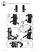
3 Change Hand of Trim (if necessary) Left Hand Reverse Right Hand Reverse There is a spring inside spindle. Be sure to keep spring for reassembly. 2 1 Nut Spindle Tighten nut then Tab loosen just enough that spindle tab aligns with top of hole. 1 1 Be sure spring is inside spindle. 2 2 1 Set screw should be located on same side as lever arm.
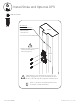
4 Install Outside Trim Assembly #10-32 x 1" OHPMS Do not take apart outside assembly. x2 Exit Device Mounting Holes 2 hinge side screws hold outside trim assembly until exit device is installed. 1 All 4 screws MUST be used for proper installation. Do not tighten screws until exit device installation -Step 5.
5 Install Exit Device #10-32 x 1" PHMS x2 Refer to exit device installation instructions for details of device installation. 3 Tighten all screws.
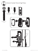
6 Install Strike and Optional DPS #10-24 PFHMS x3 DPS Option for Privacy Function Frame *Metal Frame: 3/4" Dia. x 1" See Instructions with DPS Kit *Supplied plastic collar MUST be installed for DPS to function properly. 3-1/2" Strike must be centered with exit device bolt. For proper engagement, door should remain latched and not rattle when pushed, pulled or shaken in/out. Refer to exit device installation instructions for details of strike installation.
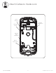
7 Install Inside Mounting Plate OR x2 #8 x 3/8" PRH Sheet Metal x2 #8 x 1/2" PHWS Wood x1 #10-32 x 1-1/2" THPMS Inside of Door Optional DPS 1 2 Part of ASSA ABLOY 9 80-8470-0900-000 04-21
8 Attach Cables to Inside Lock Reset Button Keypad Connection External Power Optional DPS Connection Motor Connection Part of ASSA ABLOY 10 80-8470-0900-000 04-21
9 Install Inside Lock #8-32 x 5/16" PHMS x3 Avoid crimping cables! Do not tighten screws until lock is flat against plate without excessive pressure.