OPERATION, SERVICE & PARTS MANUAL Before installing hoist, fill in the information below. Refer to the Hoist and Motor data plates. Model No. __________________ Serial No. __________________ Purchase Date __________________ GLOBAL KING WIRE ROPE HOISTS TM RATED THRU 10 METRIC TONNE Voltage __________________ Rated Load __________________ Follow all instructions and warnings for inspecting, maintaining, and operating this hoist.
FORWARD This book contains important information to help you install, operate, maintain and service your new Yale electric hoist. We recommend that you study its contents thoroughly before putting the hoist into use. Read HST 4M performance standard and ANSI B30.16 safety standard for hoists. Then, through proper installation, application of correct operating procedures, and by practicing the recommended maintenance suggestions you can expect maximum lifting service from the hoist.
NOTICE: Information contained in this book is subject to change without notice. INDEX SECTION I GENERAL DESCRIPTION PAGE Paragraph 1-1 General ………………………………………………………………………………………………. 4 Paragraph 1-2 Basic Construction …………………………………………………………………………………. 4 SECTION II INSTALLATION Paragraph 2-1 General ……………………………………………………………………………………………….
SECTION I – GENERAL DESCRIPTION 1-1. GENERAL. Yale “Global King” electric hoists are wire rope and drum type hoists that are manufactured with an integral trolley. These hoists are all low headroom models with the drum and upper block (or dead-end anchor depending on the reeving type) on opposite sides of the beam suspending the trolley. There are two basic frame sizes each with two standard lifts: the “B” Frame handles capacities up to 5 tonne; and the “C” Frame handles capacities up to 10 tonne.
The trolley width shall be adjusted by loosening the jam nuts on the traverse drive side of the threaded rods at each end of the hoist. If necessary, lubricate the frame alignment bars with penetrating oil before attempting to adjust trolley width. The trolley side may then be pushed or driven into position by turning the adjusting nuts on the treaded rods. Adjust nuts on each side of the hoist simultaneously to avoid binding.
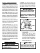
(3) Operate “UP” button briefly to determine direction of hook travel. (2) A geared rotary type upper and lower limit switch is also provided as standard. This switch is adjustable and although roughly preset by the factory, it should be adjusted at time of installation to the desired high and low limits of lower block travel. Refer to SECTION VII, Paragraph 7-3. (4) If hook raises when “UP” button is depressed, phasing is correct.
d) Depress push button marked “LEFT” to traverse in the opposite direction. CAUTION Excessive “jogging” will cause premature burning of contact tips, motor overheating, and premature brake wear. e) On two-speed hoist or trolley motions, partial depression of a button operates hoist or trolley at slow speed; depressing button completely operates hoist or trolley at full speed. 3-3. OPERATING PRECAUTIONS. Safe operation of an overhead hoist is the operator’s responsibility.
dd) DO NOT use limit switches as routine operating stops unless recommended. They are emergency devices only. ee) DO NOT use hoist to lift, support, or transport people. ff) DO NOT lift loads over people. gg) DO NOT leave a suspended load unattended unless specific precautions have been taken. hh) DO NOT allow sharp contact between two hoists or between hoist and obstructions. ii) DO NOT allow the rope or hook to be used as a ground for welding.
e) FIGURE 4-1. View of Hoist Showing Location of Name Plates and Oil Plugs. b) Remove oil drain plug from bottom of gearcase and drain oil out. Dispose of oil in accordance with local environmental codes. WARNING Avoid skin contact with Mobilsol A. In case of skin contact: dry wipe the skin, cleanse the area with a waterless hand cleaner and follow by washing thoroughly with soap and water. c) Reinstall drain plug. d) Remove oil level plug from front of gearcase cover.
4-7. LUBRICANT SPECIFICATIONS. GCOH Gear Case Oil. Hoist Gear Case. SG Spline Grease NLGI Grease ASTM D217 Worked Penetration Dropping Point Base Mobil Oil Corp. No. 6 1335 - 1632 SUS 154 -40°F Mobil SHC 632 Omala RL 320 Pinnacle 320 No. 7 EP 1919 - 2346 SUS 95 20°F Mobilgear 634 Omala 460 Meropa 460 No. 7 1919 - 2346 SUS 158 -37°F Mobil SHC 634 Omala RL 460 Pinnacle 460 No.
4-7. LUBRICANT SPECIFICATIONS CONT’D. GCOT Gear Case Oil. Traverse Gear Case. AGMA Lubricant ISO Viscosity Grade American Lubricants Mobil Oil Corp. Shell Oil Co. Fiske Brothers Texaco Inc. AMBIENT TEMPERATURE -20° to 50°F (-29° to +10°C) 50° to 100°F (10° to 38°C) 100° to 250°F (38° to 121°C) No. 5S 220 SHC 90W Mobil SHC 630 Omala RL 220 SPO-MG Pinnacle 220 No.
The user should revise the inspection interval, add additional units or provide a similar form to suit particular conditions that may exist. However, written, dated and signed inspection reports should be maintained particularly on critical items such as hoist hooks, hoisting rope, sheaves, drums and brakes. Periodic review of old inspection reports can point out service life of hoist components, forecasting need for adjustment, repair or replacement of these components.
INSPECTION SCHEDULE AND MAINTENANCE REPORT HOIST SERIAL NO.
WARNING Do not operate a hoist having unusual vibrations, sounds, or with anything wrong or apparently wrong. Danger may be present that the hoist operator cannot see. Determine and correct the cause of unusual conditions and make certain hoist can be operated safely. g) Hooks showing signs of cracks must be replaced. Hooks should be inspected at least once per year using dye penetrants, magnetic particle, or other suitable nondestructive test methods.
securely crimped to wires and insulation sound. Terminal screws should be tight. b) Check condition of contactor assembly, transformer, and upper limit switches. WARNING Check to be certain main power switch is locked in open position (OFF) before removing brake cover. 5-5. INSPECTION OF ROPE GUIDE. a) General. The rope guide is intended to help prevent the rope from “back-winding” and to hold the rope in the proper groove.
wire ropes will eventually deteriorate to a point where they are not safe and will require replacement. Wire rope should be thoroughly inspected at regular monthly intervals by an authorized person and a determination made when further use of the rope would constitute a safety hazard. Each inspection should include a written dated and signed report of rope condition. Reports should be filed and reviewed each month and any rope deterioration carefully noted.
CAUTION It is imperative that rope reel or coil rotates as rope unwinds. If coil or reel does not rotate the wire will be twisted as it is uncoiled and kinking will result. A kinked rope may be damaged and unsafe for maximum service. b) Before removing the old rope, refer to reeving diagram, Figure 5-6. To assist with re-reeving your hoist, refer to the reeving diagram and corresponding paragraph that describes the reeving procedure. c) Removing old rope.
torque the remaining two (2) rope clamps in sequence to 50 ft-lbs. (2) With all personnel clear of hoist – TURN ON POWER. (3) Operate hoist “UP” guiding six (6) wraps of new rope into drum grooves with gloved hand. (3) Re-install rope guide over rope in rope drum grooves as shown in Figure 5-3. and outlined in Section V, Paragraph 5-6. Continue lubricating as rope is spooled onto the drum until about 28’-0” remain unwound.
spur. The gear shafts are supported with ball bearings housed in the back of the case and in the cover. The input helical pinion is cut directly into the motor shaft. An oil seal housed in the gear case at the motor input seals the motor shaft as it passes into the gear case. Since the entire motor shaft is submerged in oil, anytime the motor is removed, the oil must be drained from the gear case. All pinions are integral with their shafts while the gears are keyed and pressed onto their shafts.
(4) Disconnect the wiring and conduit from the motor junction box. (12) Test hoist to ensure proper operation per Section V, Paragraph 5-13. (5) Provide a means to support the hoist motor. The hoist motor weighs approximately 250 lbs. And must be held level while removing and installing. 5-10. INSPECTION OF MOTOR BRAKE AND ACTUATING MECHANISM. (6) Once the motor is properly supported, remove the hardware fastening it to the gear case.
(2) Make sure power to the hoist is off and locked out. achieved. The air gap must be the same all the way around the brake. Once the air gap is correct, torque the mounting bolts to the value shown in Table 5-1. (3) Remove the four (4) bolts attaching the fan shroud to the motor and remove the fan shroud. See Figure 5-9. (8) Replace the large O-ring over the air gap and reassemble the fan shroud to the motor.
(3) Connect the brake leads to the terminal block on the brake body. (4) Install the forward fan mounting retaining ring and install the fan. Install the rear retaining ring. Install the fan shroud and bolts. (5) Test hoist per Section V, Paragraph 5-13. 5-11. INSPECTION DRIVE. OF HOIST TRAVERSE Figure 5-10. Traverse Drive Arrangement. a) General. The traverse drive consists of four single flange wheels, two on each side of the beam, carried directly by the hoist frame.
b) Procedure. Remove load from the hook. To disconnect the geared limit switch refer to Figure 7-2. Remove the limit switch cover then loosen the two (2) screws holding the locking plate in place. Allow the locking plate to slide down and disengage from the adjustment discs. Do not rotate the adjustment discs. CAUTION Damage to the hoist may occur if the block operated limit switch fails during testing.
SECTION VI – TROUBLE SHOOTING WARNING 6-1. GENERAL. This section contains possible causes and solutions to common hoist problems. Please attempt to remedy your hoist problems by following these steps before contacting the factory. Working in or near exposed energized electrical equipment presents the danger of electric shock. TO AVOID INJURY: DISCONNECT POWER AND IMPLEMENT LOCKOUT/TAGOUT PROCEDURE BEFORE REMOVING COVER OR SERVICING THIS EQUIPMENT.
TROUBLE 6-4 Hook Will Lower, But Not Raise. 6-5 Hoist Will Not Lift Rated Load. 6-6 Hoist Motor Overheats. 6-7 Load Drifts Excessively When Hoist is Stopped. 6-8 Hoist Operates Intermittently. SECTION VI – TROUBLE SHOOTING PROBABLE CAUSE REMEDY a. Reduce loading to rated load of hoist as shown on a. Excessive load. nameplate. b. Hoist electrical circuit open. b. Check for loose connections. See that necessary jumper wires are properly installed on contactor. c. Contactor assembly not functioning. c.
This limit switch has a rotary screw driven by a gear reduction that is coupled to the end of the drum shaft. Adjustment discs operate the contacts of separate switches, one for the hoisting circuit and one for the lowering circuit. The switch assembly must be wired in accordance with the appropriate wiring diagram, which is shipped with the hoist. Instructions for adjusting limit switch are inside cover and are repeated below (see Figure 7-2).
Figure 8-1. Elementary Wiring Diagram for a Two-Speed Hoist and Two-Speed Trolley with TAS, Hoist Block Operated Limit Switch, Geared Upper & Lower Limit Switches, and Optional Fuses.
Figure 8-2. Component Diagram for a Two-Speed Hoist and Two-Speed Trolley with TAS, Hoist Block Operated Limit Switch, Geared Upper & Lower Limit Switches, and Optional Fuses.
SECTION IX – PARTS LIST 9-1. GENERAL. The parts lists and illustrations in this section of the manual cover parts for models of Yale “Global King” Electric hoists. A typical hoist is shown as the basis for the exploded parts illustrations; therefore, certain variations may occur from the information given. For this reason, always give the Hoist Serial Number, Catalog Number, Motor Horsepower, Voltage, Phase, Frequency and Capacity of Hoist when ordering parts.
FIGURE 9-1. Hoist Drum, Drum Frame, Gearcase, Motor, Rope Guide, and Screw Type Limit Switch. “B” Frame: Hoist Components for Figure 9-1. Ref. No.
“B” Frame: Hoist Components for Figure 9-1. Ref. No. 28 29 30 31 32 33 34 35 36 Part Number GHB-128 GHB-129 GHB-130 GHB-131 GHB-132 GHB-133 GHB-134 GHB-135 GHB-136A GHB-136B Description Lockwasher (7/16) High Strength Hex Head Bolt – Grade 5 (7/16-14 x 1 1/2) High Strength Hex Head Bolt – Grade 5 (7/16-14 x 1 3/4) Outboard End Drum Frame Limit Switch Bracket Retaining Ring Drum Shaft Insert for Geared Limit Switch Geared Limit Switch Drum Frame Rod Drum Frame Rod, 25’ Lift Drum Frame Rod, 40’ Lift Qty.
Figure 9-2. Hoist Gearing. “B” Frame: Hoist Gearing for Figure 9-2. Ref. No. 1 2 3 4 5 6 7 8 9 10 11 12 13 14 15 16 17 18 19 Part Number GHB-200 GHB-201 GHB-202 GHB-203 GHB-204 GHB-205 GHB-206 GHB-207 GHB-208 GHB-209 GHB-210 GHB-211 GHB-212 GHB-213 GHB-214 GHB-215 GHB-216 GHB-217 GHB-218 GHB-216 Description Complete Hoist Gearcase Ass’y. - 94.4:1 Ratio (Incl. Ref Nos.
“C” Frame: Hoist Gearing for Figure 9-2. Ref. No.
Figure 9-3. Motor Driven Trolley Frame and Drive (“B” Frame Shown). “B” Frame: Trolley Frame and Drive Components for Figure 9-3. Ref. No.
“B” Frame: Trolley Frame and Drive Components for Figure 9-3. Ref. No.
Figure 9-4. Lower Block Assembly. “B” Frame: Lower Block Components for Figure 9-4. Ref. No. 1 2 3 4 5 6 7 8 9 10 11 12 13 14 15 16 17 Part Number GHB-400Y GHB-401 GHB-402 GHB-403 GHB-404 GHB-405 GHB-406Y GHB-407 GHB-408 GHB-409 GHB-410 GHB-411 GHB-412 GHB-413 GHB-414 GHB-415 GHB-416 GHB-417 Description Lower Block Assembly (Includes Ref. Nos.
“C” Frame: Lower Block Components for Figure 9-4. Ref. No.
Figure 9-5. Upper Block Assembly. “B” Frame: Upper Block Components for Figure 9-5. Ref. No. 1 2 3 4 5 6 7 8 9 10 11 12 13 14 15 Part Number GHB-500 GHB-501 GHB-502 GHB-503 GHB-504 GHB-505 GHB-506 GHB-507 GHB-508 GHB-509 GHB-510 GHB-511 GHB-512 GHB-513 GHB-514 GHB-515 Description “B” Frame Hoist Upper Block Assembly (Includes Ref. Nos.
“C” Frame: Upper Block Components for Figure 9-5. Ref. No. 10 11 12 13 14 Part Number GHC-510 GHC-511 GHC-512 GHC-513 GHC-514 Description Internal Retaining Ring Spacer Washer Self-Locking Nut (3/8) Yoke Pin Cotter Pin Qty.
Figure 9-7. “C” Frame: Rope and Dead End Assembly. Ref. No. 1 2 3 4 5 “C” Frame: Rope and Dead End Assembly Components for Figure 9-7. Part Number Description GHC-700 “C” Frame Hoist Rope and Dead End Assembly GHC-701 Cotter Pin GHC-702 Dead End Swaged Socket Pin GHC-703 Flanged Bushing GHC-704 Washer (1 1/2" Diameter, #10 Gauge) Wire Rope and Swaged End Assembly GHC-705A Rope Assembly for 25’ lift GHC-705B Rope Assembly for 40’ Lift Figure 9-8. Block Operated Limit Switch Assembly (“B” Frame shown).
Ref. No. 1 2 3 4 5 6 7 8 9 10 11 12 13 14 15 16 Ref. No. 1 2 3 4 5 6 7 8 9 10 11 12 13 14 15 16 17 18 “B” Frame Block Operated Limit Switch Components for figure 9-8. Part Number Description GHB-800 “B” Frame Hoist Limit Switch Assembly (Includes Ref. Nos.
Figure 9-9. Rope Guide Assembly “B” Frame Rope Guide Components for Figure 9-9. Ref. No. 1 2 3 4 5 6 7 8 9 Part Number GHB-900 GHB-901 GHB-902 GHB-903 GHB-904 GHB-905 GHB-906 GHB-907 GHB-908 GHB-909 Description “B” Frame Rope Guide Assembly (Includes Ref. Nos. 1-9) Rope Guide Frame (Machined) Plastic Shroud Extension Spring Shoulder Bolt (1/4-20 x 1 1/2 Long, 5/16 Shoulder) Compression Spring Grease Fitting Anti-Rotation Clip Lockwasher (1/4) Socket Head Cap Screw (1/4-20 x 3/4) Qty.
Figure 9-10. Hoist Motor Brake. “B” Frame: Hoist Brake Components for Figure 9-10. Ref. No.
Figure 9-10. Hoist Motor Brake. “C” Frame: Hoist Brake Components for Figure 9-10. Ref. No.
Figure 9-11. “B” Frame Trolley Drive Gear Reducer. Ref. No. 1 2 3 4 5 6 7 8 9 10 11 12 13 14 15 16 17 18 19 20 21 22 23 24 25 “B” Frame Trolley Drive Gear Reducer Components for Figure 9-11. Part Number Description GHB-309A “B” Gear Reducer, 30:1 Ratio – 50 FPM (Includes Ref. Nos. 1-25) GHB-309B “B” Gear Reducer, 20:1 Ratio – 75 FPM (Includes Ref. Nos.
Figure 9-12. “C” Frame Trolley Drive Gear Reducer. Ref. No. 1 2 3 4 5 6 7 8 9 10 11 12 13 14 15 16 17 18 19 20 21 22 23 24 25 46 “C” Frame Trolley Drive Gear Reducer Components for Figure 9-12. Part Number Description GHC-309A “C” Gear Reducer, 30:1 Ratio – 50 FPM (Includes Ref. Nos. 1-25) GHC-309B “C” Gear Reducer, 20:1 Ratio – 75 FPM (Includes Ref. Nos.
NOTES __________________________________________________________________________ __________________________________________________________________________ __________________________________________________________________________ __________________________________________________________________________ __________________________________________________________________________ __________________________________________________________________________ ________________________________________________________
Recommended Spare Parts Certain Parts of your hoist will, in time, require replacement under normal wear conditions. It is suggested that the following parts be purchased for your hoist as spares for future use. One Brake Friction Disc One Brake Module One Set of Contactors One Transformer One Wire Rope Assembly Note: When ordering parts always furnish Hoist Serial Number, Catalog Number, Motor Horsepower, Voltage, Phase, Frequency and Rated Load of Hoist on which the parts are to be used.