
User manual

P 20
2.
"!!
!!
#.
#.
& !#
! !!
!! !
"!!
!!
!
"
<!!
1
3.
!
$!
%!"!
!!"°
$!
(Adjust the location of the screws)
$%
&
This print bed has been factory calibrated before shipping. Recalibration
is necessary if there are print issues when starting to print or the nozzle
gets too close to the print bed. When in doubt, it is recommended to con-
tact service center for more information.
Print bed adjustment flow chart
Perform again!
Step
12345
Step Step Step Step
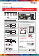
Print bed adjustment steps
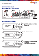
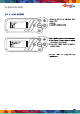
&OLFN³,1)2!6<67(09(56,21´XVLQJWKH
IXQFWLRQNH\VWRPDNHVXUH\RXUILUPZDUHLVWKH
latest.
&OLFN³87,/,7,(6!&$/,%5$7(´XVLQJWKH
IXQFWLRQNH\VDQGVHOHFW³<HV´WRSHUIRUP
print bed measurement.
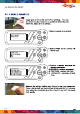
The printer starts automatic measurement. Wait
for 2~3 minutes and verify the data shown.
Note: During the measurement process, the
print bed and print module will be heated.
Care should be taken during operation!
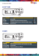
I
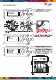
. If SUCCESS is shown.
II. If FAIL is shown.
ĺ,IWKHYDOXHVDUHPRUHWKDQIURPHDFKRWKHUWKLVZLOO
result in a "FAIL" calibration.
3ULQWEHGOHYHOLQJLVQHFHVVDU\UHIHUWRWKHYDOXHVVKRZQ
ĺ$GMXVWPHQWWRWKHSULQWEHGLVXQQHFHVVDU\3UHVVOKWRH[LW
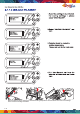
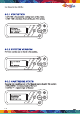
Tip II. View the printer from the front
ZKHQPDNLQJDGMXVWPHQW
8VHVPDOOGLDOWXUQVWRDSSUR[LPDWHWKHGHVLUHGYDOXH
Rotate the screw to the left to
raise the bed (value increases)
Rotate the screw to the right to
lower the bed (value decreases)
Refer to the values for adjustment:
$IWHUDGMXVWLQJWKHVFUHZVSOHDVHUXQ&DOLEUDWH
VHHVWHS,IWKHVFUHHQUHSHDWV)$,/SOHDVH
continue the steps for calibration. Until "SUCCESS" is
VKRZQRQVFUHHQSUHVV2.WRFRPSOHWHWKHFDOLEUD
tion.
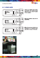
If the value shown is always ERR,ERR,ERR
follow the steps below to clean.
烋 Reminder
A. Clean the surface of the print head using
the copper brush.
(Clean the contact point between the print head
and print bed)
B. Wipe and clean the measurement
SRLQWVDVVKRZQRQWKHSULQWEHGLQVWHS
C. Perform the calibration process again.
Note: 3 values shown on screen indicate the distance between
WKHGHWHFWSLQE\WKHQR]]OHDQGWKHHGJHRIWKHSULQWEHG,I
DQ\YDOXHLVRXWRIWKHUDQJHRIWRSOHDVHDGMXVWWKH
value by turning the screw(s) under the print bed.
Tip I. Value set and corresponding thumbscrew:
(Location of the measurement points)
7RFOHDQWKHPROWHGILODPHQWIURPQR]]OHWKRURXJKO\LWLV
UHFRPPHQGHGWRDFWLYDWH³&/($112==/(´IXQFWLRQWR
NHHSKHDWLQJWKHH[WUXGHUVIRUEHWWHUFOHDQLQJ
!
-(03
+,+,+
[]!!"
!
"
+, +,+
[]! #
!
"
+, +,+
[]! #
!
-(03
+,+,+
[]!!"
!
-(03
(55(55(55
[]!!"