
Manual

27
03
Operations
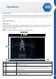
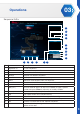
11. Select Tool > Pose Editor.
12. Under Pose List, click Add to create a new pose.
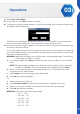
13. The New pose settings window displays. In the Pose name field, enter a name for the pose and
click Ok to create the new entry.
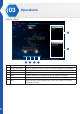
The New Pose is configured with the default settings. This function allows you to create pose
entries which can be modified and saved, and used to create sequence entries.
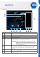
14. Now that the pose is created, it appears in the Pose List column. Locate your desired pose entry
and select it to edit the settings.
You can edit a pose by one of two ways, physically move the smart servo position or through the
use of the slide bar function in the Pose Editor. The following instructions provide a step-by-step
instructions of both procedures.
WARNING: Keep hand and fingers out of the joint areas to avoid getting caught. To avoid injury,
do not place your hands in any joint.
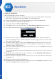
a. In the bottom toolbar, click Relax to release the smart servos and allow you to move them
freely.
NOTE: To avoid damage the Robotic Arm, please lay it down or grip it firmly by the bar on
the back of the Robotic Arm (over the power switch), before clicking the Relax.
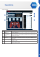
b. Select a smart servo and adjust it to a desired position. This is the position that will be
associated with the selected pose.
c. Click Capture to save the settings to the selected Pose.
d. Click Set after adjusting slide bars.
OR
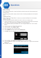
a. Select a pose from the Pose List.
b. Click Live Pose Update to adjust the actual position of a selected smart servo.
c. Select a smart servo, and adjust the slide bar to a desired smart servo position.
d. Click Set after adjusting slide bars.
WARNING: Each servo has a limited control range:
• ID1: 0 ~ 1023
• ID2: 234 ~ 742
• ID3: 252 ~ 790
• ID4: 152 ~ 782
• ID5: 128 ~ 896
• ID6: 512 ~ 852