
User guide

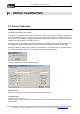
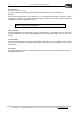
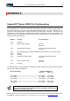

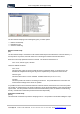
Table Of Contents
- Version: V2.7.1.2
- Contents
- 1 INSTALLATION and OVERVIEW
- 2DEVICE CONNECTION
- 3ENGINEERING RESOURCES
- 4MANAGING PROFILES
- 5MANAGING LOGGED DATA
- 6CONFIGURING DATALOGGERS
- 6.1 Introduction
- 6.2 DS-CPU3 Configuration
- 6.3 DS-4483 Configuration
- 6.3.1 DS-4483 Sensor Configuration Settings
- 6.3.1.1 Retrieving the Datalogger Configuration
- 6.3.1.2 Transferring Configuration Settings to the DS-4483
- 6.3.1.3 Loading a Template into iLink
- 6.3.1.4 Saving a Template to file
- 6.3.1.5 Printing Template Information
- 6.3.1.6 Sensor Selection
- 6.3.1.7 General Setup
- 6.3.1.8 I/O Setup
- 6.3.1.9 Scaling Setup
- 6.3.1.10 Timing/Misc Setup
- 6.3.1.11 Alarms Setup
- 6.3.1.12 Output Setup
- 6.3.1.13 Comment Setup
- 6.3.2 Telemetry Communications Control Configuration
- 6.3.4 New Sensor Wizard
- 6.3.1 DS-4483 Sensor Configuration Settings
- 7LOADING PROGRAMS
- 8DEVICE CALIBRATION
- APPENDIX A
- APPENDIX B
- APPENDIX C
- APPENDIX D
62 iLink - Configuration and Support Utility
iQuest (NZ) Ltd - PO Box 15169 HAMILTON Tel: +64 7 957 8160 - Fax: +64 7 957 8162 - Email: iquest@iquest.co.nz
Modem Busy Signal
{Active when Low, Active when High}
For radio connections this should be set to match the ‘Busy Polarity’ of the connected radio.
Rel TX Level
The minimum permitted value is 0, the maximum is 15. If using the internal modem to connect to a radio,
a setting of 7 is normal. If connected to a PSTN interface, a value of 12 should be used to comply with
New Zealand Telecom’s Telepermit line levels.
The remaining settings are pre-set at time of manufacture and should not require
alteration under normal circumstances.
Battery Volts / Offset
The last reading taken for internal battery voltage is displayed here. It is possible to enter an offset here,
which is incorporated in the reading and logged values (if the internal battery voltage is set up as an active
sensor).
Temperature / Offset
The last reading taken for internal device temperature is displayed here. It is possible to enter an offset
here, which is incorporated in the reading and logged values (if the internal temperature is set up as an
active sensor).
RTC Calibration
This setting should be left at zero. It is provided to offset any ‘drift’ in the device real-time clock that may
be experienced over time.