
User guide
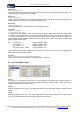
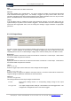
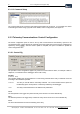
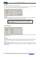
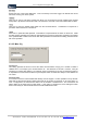
Table Of Contents
- Version: V2.7.1.2
- Contents
- 1 INSTALLATION and OVERVIEW
- 2DEVICE CONNECTION
- 3ENGINEERING RESOURCES
- 4MANAGING PROFILES
- 5MANAGING LOGGED DATA
- 6CONFIGURING DATALOGGERS
- 6.1 Introduction
- 6.2 DS-CPU3 Configuration
- 6.3 DS-4483 Configuration
- 6.3.1 DS-4483 Sensor Configuration Settings
- 6.3.1.1 Retrieving the Datalogger Configuration
- 6.3.1.2 Transferring Configuration Settings to the DS-4483
- 6.3.1.3 Loading a Template into iLink
- 6.3.1.4 Saving a Template to file
- 6.3.1.5 Printing Template Information
- 6.3.1.6 Sensor Selection
- 6.3.1.7 General Setup
- 6.3.1.8 I/O Setup
- 6.3.1.9 Scaling Setup
- 6.3.1.10 Timing/Misc Setup
- 6.3.1.11 Alarms Setup
- 6.3.1.12 Output Setup
- 6.3.1.13 Comment Setup
- 6.3.2 Telemetry Communications Control Configuration
- 6.3.4 New Sensor Wizard
- 6.3.1 DS-4483 Sensor Configuration Settings
- 7LOADING PROGRAMS
- 8DEVICE CALIBRATION
- APPENDIX A
- APPENDIX B
- APPENDIX C
- APPENDIX D
iQuest (NZ) Ltd - PO Box 15169 HAMILTON Tel: +64 7 957 8160 - Fax: +64 7 957 8162 - Email:
iLink - Configuration and Support Utility 43
iquest@iquest.co.nz
Maximum Raw
Applies to: Analogue Input
This setting indicates the maximum raw value that can be stored for this particular analogue input. It is
unlikely that this setting will need to be altered.
Minimum E.U
Applies to: Analogue Input
Values output by the sensor are converted to actual Engineering Units (E.U) by the logger program. This
setting specifies the minimum value in actual engineering units.
Maximum E.U
Applies to: Analogue Input
This setting specifies the maximum value in actual engineering units.
Logging Mult
Applies to: All Input Types
{1, 10, 100, 1000, 0.1, 0.01, 0.001}
The logging multiplier setting is used to convert the actual values (in Engineering Units) into integer values
for storage in the logger database. Thus in the screenshot above, in order to convert the E.U values of 0
– 5 into the stored values of 0 – 4095 a multiplier of 1000 is required. Other ranges of E.U values may
require different logging multipliers to bring them within the range 0 – 4095. Select the most appropriate
logging multiplier from the list.
E.g. E.U Range: 0 – 1 Logging multiplier: 1000
E.U Range: 0 – 2 Logging multiplier: 1000
E.U Range: 0 – 10 Logging multiplier: 100
E.U Range: 1000 – 10000 Logging multiplier: 0.01
When working with unloaded logged data, the multiplier is used in reverse to return the logged values
back to their correct Engineering Units.
Scale Factor
Applies to: Counter, SDI-12, Sync serial, Up/Dn Encoder, Derived
This is used to specify the scale factor for digital devices, e.g. SDI-12.
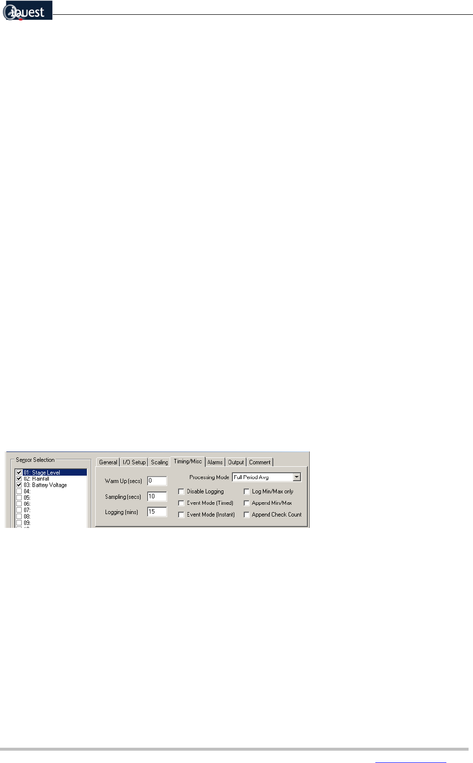
6.3.1.10 Timing/Misc Setup
Warm Up
This setting is only applicable if the sensor is to be powered by the logger (using a Control Output). It
specifies the number of seconds to turn on the sensor before each reading is taken. If this value is zero,
the sensor will be permanently powered up.
Sampling
Enter the sampling frequency here. This setting specifies how often the logger will take a reading from the
sensor.
Logging
Enter the logging interval here. This setting specifies how often the DS-4483 will log a value for this
sensor. See also Event Mode (Timed) and Event Mode (Instant) below.