
User guide
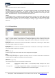
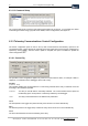
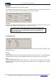
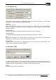
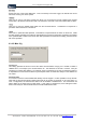
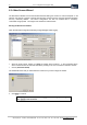
Table Of Contents
- Version: V2.7.1.2
- Contents
- 1 INSTALLATION and OVERVIEW
- 2DEVICE CONNECTION
- 3ENGINEERING RESOURCES
- 4MANAGING PROFILES
- 5MANAGING LOGGED DATA
- 6CONFIGURING DATALOGGERS
- 6.1 Introduction
- 6.2 DS-CPU3 Configuration
- 6.3 DS-4483 Configuration
- 6.3.1 DS-4483 Sensor Configuration Settings
- 6.3.1.1 Retrieving the Datalogger Configuration
- 6.3.1.2 Transferring Configuration Settings to the DS-4483
- 6.3.1.3 Loading a Template into iLink
- 6.3.1.4 Saving a Template to file
- 6.3.1.5 Printing Template Information
- 6.3.1.6 Sensor Selection
- 6.3.1.7 General Setup
- 6.3.1.8 I/O Setup
- 6.3.1.9 Scaling Setup
- 6.3.1.10 Timing/Misc Setup
- 6.3.1.11 Alarms Setup
- 6.3.1.12 Output Setup
- 6.3.1.13 Comment Setup
- 6.3.2 Telemetry Communications Control Configuration
- 6.3.4 New Sensor Wizard
- 6.3.1 DS-4483 Sensor Configuration Settings
- 7LOADING PROGRAMS
- 8DEVICE CALIBRATION
- APPENDIX A
- APPENDIX B
- APPENDIX C
- APPENDIX D
42 iLink - Configuration and Support Utility
iQuest (NZ) Ltd - PO Box 15169 HAMILTON Tel: +64 7 957 8160 - Fax: +64 7 957 8162 - Email: iquest@iquest.co.nz
Counter
Channel
{P1, P2}
Select the channel to which the sensor is connected.
SDI-12
Address
{0,1,2,3,4,5,6,7,8,9}
Select the address of the sensor on the SDI-12 bus.
Variable
{1,2,3,4,5}
Select the variable for the sensor.
Sync Serial
No other I/O settings are required for this type of input.
Battery Volts
No other I/O settings are required for this type of input.
Internal Temp
No other I/O settings are required for this type of input.
Up/Dn Encoder
No other I/O settings are required for this type of input.
Derived
Currently, only one type of derived input is supported. This is a lookup function. A lookup table can be
loaded into the DS-4483 logger and used to generate a derived input. For example, a derived ‘sensor’
could be based on a stage level sensor and use the lookup table to output corresponding flow levels.
Sensor
{1,2,3,4,5,6,7,8,9,10,11,12,13,14,15,16,17,18,19,20}
Select the number of the sensor that is to provide the input for the lookup function.
Function
{Lookup}
Select ‘Lookup’ from the drop-down list.
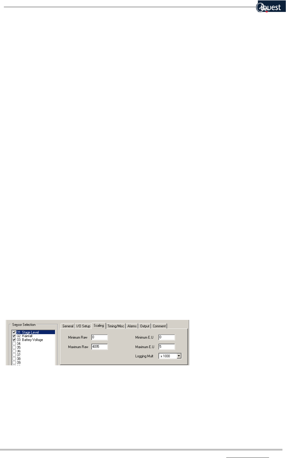
6.3.1.9 Scaling Setup
Not all of the settings listed below apply to every type of input. For example the Minimum Raw, Maximum
Raw, Minimum E.U and Maximum E.U apply only to Analogue Inputs. The applicability of each setting is
indicated as appropriate.
Minimum Raw
Applies to: Analogue Input
All logged values stored within the logger are stored as integers. This setting indicates the minimum raw
value that can be stored for this particular analogue input. It is unlikely that this setting will need to be
altered.