
User guide
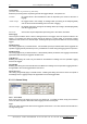
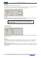
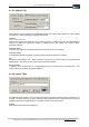
Table Of Contents
- Version: V2.7.1.2
- Contents
- 1 INSTALLATION and OVERVIEW
- 2DEVICE CONNECTION
- 3ENGINEERING RESOURCES
- 4MANAGING PROFILES
- 5MANAGING LOGGED DATA
- 6CONFIGURING DATALOGGERS
- 6.1 Introduction
- 6.2 DS-CPU3 Configuration
- 6.3 DS-4483 Configuration
- 6.3.1 DS-4483 Sensor Configuration Settings
- 6.3.1.1 Retrieving the Datalogger Configuration
- 6.3.1.2 Transferring Configuration Settings to the DS-4483
- 6.3.1.3 Loading a Template into iLink
- 6.3.1.4 Saving a Template to file
- 6.3.1.5 Printing Template Information
- 6.3.1.6 Sensor Selection
- 6.3.1.7 General Setup
- 6.3.1.8 I/O Setup
- 6.3.1.9 Scaling Setup
- 6.3.1.10 Timing/Misc Setup
- 6.3.1.11 Alarms Setup
- 6.3.1.12 Output Setup
- 6.3.1.13 Comment Setup
- 6.3.2 Telemetry Communications Control Configuration
- 6.3.4 New Sensor Wizard
- 6.3.1 DS-4483 Sensor Configuration Settings
- 7LOADING PROGRAMS
- 8DEVICE CALIBRATION
- APPENDIX A
- APPENDIX B
- APPENDIX C
- APPENDIX D
iQuest (NZ) Ltd - PO Box 15169 HAMILTON Tel: +64 7 957 8160 - Fax: +64 7 957 8162 - Email:
iLink - Configuration and Support Utility 41
iquest@iquest.co.nz
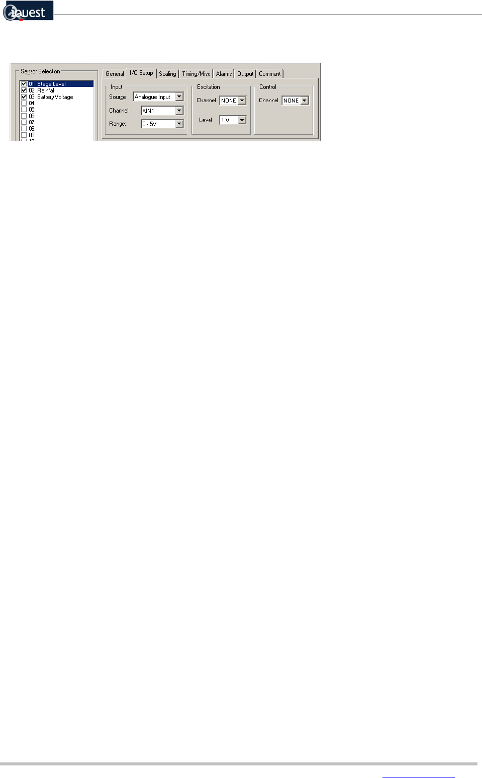
6.3.1.8 I/O Setup
Input Source
{Analogue input, Pulse input, Counter, SDI-12, Sync serial, Battery volts, Internal Temp, Up/Dn Encoder, Derived}
Use this setting to specify the type of input that will be read in from the sensor. Select the appropriate
option from the list provided.
Depending on the input source selected, other options may be become enabled or disabled. Each of
these are detailed in turn below:
Analogue Input
Input Channel
{AIN1, AIN2, AIN3, AIN4, AIN5, AIN6, AIN7, AIN8}
Select the input channel to which the sensor will be connected. There are 8 available analogue input
channels from which to choose.
Input Range
{0 – 1V, 0 - 2V, 0 - 2.5V, 0 - 5V, 4 – 20 mA, -2.5V to + 2.5V, CS107B, 0 – 100mV}
Select the appropriate input range from the list provided. Refer to the individual sensor documentation for
help with this setting.
Excitation Channel
{None, V01, V02, V03}
Specify the excitation channel if required. There are three excitation channels from which to choose. If an
excitation channel is required, the excitation level must also be set.
Excitation Level
{1V, 2V, 2.5V, 5V}
Set the required voltage level to be output on the excitation channel selected above.
Control Channel
{None, D01, D02, D03, D04}
This setting only applies if the selected sensor is powered by the logger, via one of the control ports D01 –
D04. If the ‘warm-up’ time is zero the sensor is powered continuously, otherwise the sensor is turned on
according to the warm-up time specified.
Pulse Input
Channel
{DI1, DI2, P1, P2}
Select the channel to which the sensor is connected.
Increment
{0.1, 0.2, 0.5, 1.0, 2.0, 5.0, 10.0}
Select the corresponding value to increment on each pulse.