iLink User Guide Version: V2.7.1.
iLink - Configuration and Support Utility Amendments: Issue 1 Issue 2 Issue 3 September 2000 May 2002 February 2004 Disclaimer Under no circumstances will iQuest (NZ) Ltd be liable or responsible for any consequential damage or loss that may arise from the use of this product. All examples and diagrams shown in this manual and all supplied software examples are intended as a guide to understanding this product, not to guarantee operation.
iLink - Configuration and Support Utility 3 Contents CONTENTS 3 1 INSTALLATION AND OVERVIEW 5 2 3 4 5 1.1 Introduction 1.1.1 Supported System DO® Products 1.1.2 Unsupported System DO® Products 1.2 Installing the iLink Application 1.2.1 iLink File Structure 1.3 Using the Manual 1.3.1 Menu Items 1.3.2 Command Buttons 1.3.3 Dialog Options 1.3.4 Option Lists 1.3.5 Notes 1.4 Registration 1.5 Navigation 1.6 Communications 1.7 Profiles 1.8 Templates 1.
6 7 8 iLink - Configuration and Support Utility CONFIGURING DATALOGGERS 34 6.1 Introduction 6.2 DS-CPU3 Configuration 6.2.1 DS-CPU3 Configuration Settings 6.2.2 Examples of Sensor Configurations for DS-CPU3 6.2.3 Transferring Sensor Configurations to the DS-CPU3 6.2.4 Saving the Sensor Configuration 6.3 DS-4483 Configuration 6.3.1 DS-4483 Sensor Configuration Settings 6.3.1.1 Retrieving the Datalogger Configuration 6.3.1.2 Transferring Configuration Settings to the DS-4483 6.3.1.
iLink - Configuration and Support Utility 5 1 INSTALLATION and OVERVIEW 1.1 Introduction Thank you for purchasing iLink. iLink is a utility program used for communicating with the range of System DO® products manufactured by iQuest (NZ) Ltd.
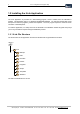
iLink - Configuration and Support Utility 1.2 Installing the iLink Application The iLink Application is provided as a self-installing program, which is loaded, from the CD-ROM or website. This application will run on Windows 95/98/NT/Me/2000/XP. You will need at least 5Mb of free disk space to load the programs, profiles and templates. The iLink program requires a minimum screen resolution of 640x480 pixels. To load this application, run Setup.exe from the CD-ROM.
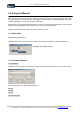
iLink - Configuration and Support Utility 7 1.3 Using the Manual This manual is provided to give you an overview of the various features of iLink and enable you to start using the software to communicate with and program selected devices including dataloggers and also to configure dataloggers, unload data, plot data, export data.
iLink - Configuration and Support Utility 1.3.3 Dialog Options Dialog Option Indicates an option that can be set within a dialog window. Options in the above dialog window include: Primary Data File Name, SOD Ptr, EOD Ptr, Unload File Mode 1.3.4 Option Lists {Analogue input, Pulse input, Counter, SDI-12, Sync serial} Indicates available settings or values for a specified option within a dialog window. 1.3.
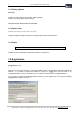
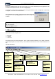
iLink - Configuration and Support Utility 9 Enter your registered name (this can be any name of 5 or more characters) and the registration code provided in the appropriate boxes and click on [Register Now]. If registration is unsuccessful, repeat the process taking special care to enter the registration code exactly as supplied. This code is not case-sensitive.
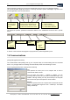
iLink - Configuration and Support Utility Options appearing as light grey text are not available with respect to the current displayed window. The tool bar provides single click access to commonly used menu options and displays only those icons that are applicable to the connected device. Disconnects PC communications to the attached device.
iLink - Configuration and Support Utility 11 Retries Defines the number of data packet retries before a communications failure (from the computer to the device) is logged. A communications circuit will exist but the actual transfer of data will have been unsuccessful. The default setting is 3. Timeout: Sets the timeout (in milliseconds) before a data packet retry is attempted. If using a low speed connection ensure sufficient time is allowed for the data packets to be transferred successfully.
iLink - Configuration and Support Utility iLink supports 3 modes of communication to external devices. Select the mode you are using from the drop-down list. Telephone Modem Type: If you are using a phone connection (PSTN/Cellular selected for Communications Mode), you will need to select the type of modem you are using here. Phone Number: If you are using a phone connection (PSTN/Cellular selected for Communications Mode), you will need to specify the phone number here.
iLink - Configuration and Support Utility 13 The Profile is automatically updated by iLink as the User communicates with the device and defines the User parameters.
2 iLink - Configuration and Support Utility DEVICE CONNECTION iLink uses the settings in the currently loaded profile when a connection is attempted to an external device. 2.1 Getting Connected [File] [Connect to Device] Having loaded and/or set up the correct profile you can now connect to the device using the toolbar [Connect] icon or menu option.
iLink - Configuration and Support Utility 3 15 ENGINEERING RESOURCES 3.1 Keypad and LCD Emulation [View] [Keypad/LCD] This option applies only when connected to a DS-4483 Datalogger. In emulating the keypad and display, iLink is reading the virtual keypad and display information from the database locations in the device. The emulated keypad and display operate in the same manner as the keypad and display on the datalogger. The buttons can be clicked with the mouse to emulate the device keypad.
iLink - Configuration and Support Utility 3.2.1 Integer Database [View][Databases etc][Integer] The database structure is similar to that of a spreadsheet with the addresses listed in units of 10. Start Location To set the starting location, enter the database location base unit and press . For example, if you want to view location d115, enter the base unit of 110. Location d345 would have a base location of 340. Alternatively, use the scroll bar to pan up and down the database.
iLink - Configuration and Support Utility 17 Common Database Locations Reserved Database locations that are common to all devices and are often viewed include: d50 d61 d62 d63 d64 d65 d66 d67 Device Address Hour: Set to the current hour of the day in 24 hour format (0-23). Minute: Current minute (0-59). Second ( 0-59 ): Current second (0-59). Day of Week (0-6): Set to the current day of the week (Sun=0, Sat=6) Day of Month (1-31): Current day in the month (1-31). Month (1-12): Current month (1-12).
iLink - Configuration and Support Utility 3.2.2 Floating Point Database [View][Databases etc][Floating Point] This view can be used to display the values stored in the floating-point database of the connected device. When the window is first opened, the addresses and corresponding values will be empty. To retrieve the current database values from the device, click on [Refresh]. This will instruct iLink to request the database from the device and update the display.
iLink - Configuration and Support Utility 19 The Base Level Memory window provides a window into the low-level memory areas of the device. It is a view only facility and is used for advanced debugging. The display shows the memory contents in both hexadecimal and ASCII. The ASCII section makes the identification of text strings easy. The Start Address entry box can be used to set the starting position for the displayed data, or the scroll bar can be used. Addresses must be entered in Hexadecimal.
iLink - Configuration and Support Utility A red rectangle behind an entry in the status pane indicates that the respective function is active. A red rectangle behind an entry either error pane indicates that the respective error has occurred since the error flags were last reset. In the example above, the status pane indicates that a program is loaded, the program is running and the database is locked. The LCD is not disabled, as this flag is not highlighted in the pane.
iLink - Configuration and Support Utility 21 3.3 Device Real Time Clock Synchronisation [Tools][Synchronise Device RTC] Use this feature to synchronize the real time clock in the connected device to the PC clock. Select [Tools][Synchronize Device RTC] to begin the process. Ensure that the time and date on the PC are correct (and take into account any daylight saving offsets) before synchronising the device. PC Time/Date The current time and date of the PC.
iLink - Configuration and Support Utility 3.4 SDI-12 Terminal Utility [Tools] [Advanced] [SDI-12 Terminal] Use of this utility assumes the user is familiar with SDI-12 instruments and the command set required for communication with the SDI-12 instrument. This menu option is only available when iLink is connected to a device that has an attached SDI-12 sensor. In the screenshots that follow, iLink is connected to a DS-4483 datalogger that, in turn, has a Handar Incremental Shaft Encoder attached.
iLink - Configuration and Support Utility 4 23 MANAGING PROFILES 4.1 Using the Wizard to Create a New Profile [File][New Profile] The New Profile Wizard will guide you through setting up a New Profile. Alternatively you can set up the communications ([Configuration][Communications]) and save this as a profile. Click [Next] to begin using the profile wizard. Select the device you intend to connect to using this profile. If you are not sure of the device type, select Unknown.
iLink - Configuration and Support Utility Enter the communication address of the device to which you intend to connect. If you do not know the address of the device, use –3 (except for a DS-CPU3). This is a universal address and the device will respond with its actual address on first communication. If the device is a DS-4483, you can obtain the address from the logger itself, by viewing the LCD display.
iLink - Configuration and Support Utility 25 If you have selected a dial-up connection you will now be asked to complete two additional steps: Specifying the modem Specifying the telephone number If you have selected a radio or direct connection, these steps will not apply. Select the modem that you will be using for the dial-up connection. There are a large number of modem types to choose from. Information about modem types available and their configuration strings is available in Appendix B.
iLink - Configuration and Support Utility The comment field is optional, and can be used to assign a meaningful identifier to the profile, such as ‘DS-4483 over radio link’. Finally, click on [Finish] to save the new profile. Note that the selected folder is the default folder for profiles, /iLink/Profiles. Enter a filename and click on [Save]. The profile is now saved. Click on the [Connect] icon on the toolbar, or select [File][Connect To Device] to connect to the device.
iLink - Configuration and Support Utility 27 4.2 Loading a Profile [File] [Open Profile] iLink always starts up with the last profile used already loaded (if no profiles have been saved, the default profile will be loaded). If necessary, a different profile can be loaded. Selecting [File][Open Profile] will bring up the Open Profile dialog. The currently loaded profile (if any) is indicated by the red arrow.
5 iLink - Configuration and Support Utility MANAGING LOGGED DATA 5.1 Unloading Data [Tools][Unload Logged Data] The unloading and viewing of data from a device is dependent on the device and the functionality of that device. The primary function of the device will be as a datalogger. The structure of the data file(s) will need to conform to the file structure defined in the section titled Device Configuration. Primary Data File Name This displays the directory path and file name.
iLink - Configuration and Support Utility 29 Fetching Device Pointers Click [Get Ptrs] to search the device and retrieve the start and end data pointers for the data that is stored in the device. Once the data pointers have been retrieved the data can be unloaded from the device to the computer. You can edit the pointers by over-writing the SOD (Start of Data) and EOD (End of Data) pointers. 5.1.
iLink - Configuration and Support Utility Unload All Selecting this option will cause all logged data to be unloaded from the logger. With the DS-4483 datalogger that has 1MB of storage, this can take a considerable time even at 9600 bps. Bit Time Stamping This option will be used to ensure future compatibility with logging devices and is not available in the current version of iLink.
iLink - Configuration and Support Utility 31 Auto-Split Data Arrays This allows the data for up to five arrays to be automatically placed into separate files when the data is unloaded. For each array, the following information needs to be specified: Array ID: Factor: Data Filename: The array ID for which values are to be placed in the file. The factor to apply to the logged value to obtain real engineering units in the outputted data. The name of the file where the data is to be saved. 5.
iLink - Configuration and Support Utility File Selection Click on [File] to select the data file to open. Click the button to select the logged data file that you wish to load into iLink and display in the window. View Mode Use this option to toggle between the plotted data and the raw, underlying samples. Examples of each view are shown on the next page. Array ID and Field When in plot view, these settings are used to determine which logged samples are plotted.
iLink - Configuration and Support Utility 33 5.2.2 Viewing Data in Plot Form The plots use the data values as stored in the logger that are integers. Therefore, the Y-axis values may need to be interpreted with a factor in mind. E.g. Battery voltage may be plotted as 1200 to 1500 for 12.00V to 15.00V Plot view The selected data file is plotted in the window, showing all sample values in the file. The vertical axis is scaled appropriately to enable the full range of data to be displayed.
6 iLink - Configuration and Support Utility CONFIGURING DATALOGGERS 6.1 Introduction iLink provides support for full configuration of two logging devices. These are: DS-4483 Datalogger DS-CPU3 DO Station (when programmed to act as a datalogger) Each of these devices has it's own separate configuration dialog. The dialog is opened from the [Configuration] menu. Depending on the device connected, there will either be a submenu [DS-4483 Logger] or a sub-menu [DS-CPU3 as Logger].
iLink - Configuration and Support Utility 35 6.2.1 DS-CPU3 Configuration Settings Sensor Configuration This box lists the sensors that are loaded into the DS-CPU3. Only the configurations for the ticked sensors are active in the logger. Only active sensors can have their configuration altered from this window. The fields can be changed by selecting the desired sensor from the Sensor Configuration box, clicking on the appropriate field with the mouse and making the necessary changes.
iLink - Configuration and Support Utility 6.2.2 Examples of Sensor Configurations for DS-CPU3 Some examples of sensor configurations are: Water Level #1 Rainfall In the above examples, only Water Level #1 and Rainfall are active, indicated by the tick next to each in the Sensor Configuration box. 6.2.3 Transferring Sensor Configurations to the DS-CPU3 This is achieved from the DS-CU3 configuration dialog.
iLink - Configuration and Support Utility 37 6.3 DS-4483 Configuration [Configuration][DS-4483 Logger] This section deals with configuring Templates for the DS-4483. Templates are used to manage the sensor and I/O configurations loaded into the device. Connection settings such as baud rate, dial-up telephone number, modem configuration etc are contained in the profile for the device When creating and configuring new sensors for a device it is recommended that you begin by following the New Sensor Wizard.
iLink - Configuration and Support Utility 6.3.1 DS-4483 Sensor Configuration Settings 6.3.1.1 Retrieving the Datalogger Configuration Before editing the template configuration, it is highly recommended that the current device configuration be retrieved from the datalogger. This will ensure that the configuration within the logger itself is synchronized with the configuration displayed in iLink.
iLink - Configuration and Support Utility 39 You will then be asked to confirm the update of the control information: The control information relates to the lower pane in the template configuration dialog, namely the Control, Radio, Callback, Lookup and Misc settings. These settings apply to the device, rather than the individual sensors. They are set for the device, not individually for each sensor. If you wish to update the control information, click [Yes], otherwise click [No].
iLink - Configuration and Support Utility 6.3.1.6 Sensor Selection The standard DS-4483 logger program has provision for up to 20 independent sensors. The Sensor Selection box lists all the sensors currently configured in the device. Those with a tick next to them are active in the logger. Those without a tick are not active. To toggle a sensor between active and inactive, simply click the check box next to the sensor.
iLink - Configuration and Support Utility 41 6.3.1.8 I/O Setup Input Source {Analogue input, Pulse input, Counter, SDI-12, Sync serial, Battery volts, Internal Temp, Up/Dn Encoder, Derived} Use this setting to specify the type of input that will be read in from the sensor. Select the appropriate option from the list provided. Depending on the input source selected, other options may be become enabled or disabled.
iLink - Configuration and Support Utility Counter Channel {P1, P2} Select the channel to which the sensor is connected. SDI-12 Address {0,1,2,3,4,5,6,7,8,9} Select the address of the sensor on the SDI-12 bus. Variable {1,2,3,4,5} Select the variable for the sensor. Sync Serial No other I/O settings are required for this type of input. Battery Volts No other I/O settings are required for this type of input. Internal Temp No other I/O settings are required for this type of input.
iLink - Configuration and Support Utility 43 Maximum Raw Applies to: Analogue Input This setting indicates the maximum raw value that can be stored for this particular analogue input. It is unlikely that this setting will need to be altered. Minimum E.U Applies to: Analogue Input Values output by the sensor are converted to actual Engineering Units (E.U) by the logger program. This setting specifies the minimum value in actual engineering units. Maximum E.
iLink - Configuration and Support Utility Processing Mode {Immediate, 1 Minute Avg, Full Period Avg, Wind Vector} Select the processing that is required to generate the logged sample. The options are: Immediate: the logged value is the instantaneous value as reported by the sensor at the time of logging. 1 Minute Average: the logged value is the average of readings taken (according to the Sampling Rate) over the 60 seconds immediately prior to the time of logging.
iLink - Configuration and Support Utility 45 Reset This is the value at which the alarm will be reset. Alarm Time This setting applies only to rainfall alarms. It is used to specify the duration over which the total rainfall must exceed the alarm trigger points. For example, a trigger of 10 (mm) and an Alarm Time of 30 (minutes), indicates that the alarm would be triggered if the rainfall exceeded 10 mm over any 30 minute period. All rainfall alarms for a sensor are tied to the same Alarm Time.
iLink - Configuration and Support Utility 6.3.1.13 Comment Setup The comment field is set at a device level and therefore applies to all sensors. It is provided as a means of describing the station usage, physical sensor details, sensor configurations, site layout etc. 6.3.2 Telemetry Communications Control Configuration The device configuration panel is used to set up radio communications and telemetry options for the connected DS-4483.
iLink - Configuration and Support Utility 47 Relay On Time The duration that the relay remains on when switched. For example, if the first communication for each day is at 06:00h, then every 1 hour until 23:00h, and the relay is to be on for a period of 15 minutes (900 seconds), the entries would be: Enable Sleep If this option is enabled, the logger will return to its ‘Sleep’ mode when the keypad has not been used, or external communications have not taken place, for a period of 1 minute.
iLink - Configuration and Support Utility 6.3.3.3 Callback Cfg These settings, with the exception of ‘Enable daily callback’ and ‘Time for daily callback’, are also used by the logger for a callback following a triggered alarm (if set). Callback via {Internal Modem, RS232 Port} Specify here whether the logger will use its internal modem to callback (via radio or PSTN/cellphone mode) or its RS232 port (via external modem or cellular device). This setting is also used for alarmgenerated callbacks.
iLink - Configuration and Support Utility 49 Num Blocks {16, 32, 64} Specify the size of the lookup table here. This is necessary so that the Logger can allocate the correct amount of memory prior to the upload. [Browse] Click here to open a ‘File Open’ window from which you can browse to the file containing the required lookup table. By default, iLink lists files with a .tbl extension, and looks in the /iLink/Tables folder for them.
iLink - Configuration and Support Utility 6.3.4 New Sensor Wizard The New Sensor Wizard is the recommended method of adding new sensors to a device template. It will take the user through a number of simple steps and then create the sensor using the supplied information and any necessary defaults. The sensor configuration can then be reviewed and, if necessary, customised as appropriate. The stages of the wizard are outlined below.
iLink - Configuration and Support Utility 51 Sensor Type 1. Select the sensor you wish to create. In the example above, an Aquaflex moisture probe has been selected. 2. Click [Next] to continue. Sensor Name 1. Enter a name for the sensor. A maximum of 15 characters is permitted. 2. Click [Next] to continue. Measurement Units Select the engineering units to be used with the sensor. If the unit you desire is not found in the list, you can enter your own by typing it in the edit box.
iLink - Configuration and Support Utility Display Format 1. Select the desired display format from the list of options, or accept the default suggested. 2. Click [Next] to continue. Input Channel Selection 1. Select the input channel to which the sensor is/will be connected. You will only be able to select from those channels that are appropriate to the device. In the example here, a choice of Analogue Input Channels is presented to match the Aquaflex moisture probe selected earlier. 2.
iLink - Configuration and Support Utility 53 Array ID 1. Accept the default array ID (which equates to the sensor number being configured) or uncheck the box and enter your own array ID. 2. Click [Next] to continue. Confirmation 1. If you are happy with the settings you have entered, click [Finish] to create the sensor. You can then review the settings and make any modifications necessary. 2. Alternatively, click [Back] to step back through the various steps and review your settings.
7 iLink - Configuration and Support Utility LOADING PROGRAMS 7.1 Loading An Application Program [Tools][Program Device] Application programs and/or configuration settings can be separately loaded into a device. Loading a new program or configuration setting automatically clears the device of the previous program. The default directory for all programs is ..\iLink\Programs\.extn.
iLink - Configuration and Support Utility 55 Note here that iLink has identified that only files with the extension .lgr are to be displayed, as these are the only program files that can be loaded into a DS-4483. Once the correct program has been selected, the file name and directory path will be displayed in the Program File Name field. This field can be edited at any time up to the time of initiating the [Load] command. Start the program upload to the logger by clicking on [Load].
iLink - Configuration and Support Utility The device profile will also be updated when a new program is loaded into the logger. The Control buttons are used to start/stop the loaded program and clear the device: Starting the Program After loading the program it must be started by clicking the [Start Program] button. The program will switch from an IDLE state, to the RUNNING state. The only options then available to the User are to [Stop Program] or [Clear Device].
iLink - Configuration and Support Utility 57 7.2 Loading Kernel and/or Flash Executive Files [Tools][Advanced][Flash Executive] These files are loaded as part of the manufacturing process and are unlikely to need to be reloaded by the User. The facility to load replacement programs will enable firmware upgrades to be made without returning the device to iQuest. The general process of loading these flash executive files is the same as loading an application program.
iLink - Configuration and Support Utility Once the file is selected, click on the [Update] button to initiate the update process. A confirmation dialog will be presented as a reminder that communications must not be lost during the update process. Click on [OK] to confirm that you wish to begin the update. During the update process, a progress indicator provides visual feedback of the status of the upload. Once the update is complete, a dialog will be shown confirming that the update was successful.
iLink - Configuration and Support Utility 59 The flash executive files are stored in the default firmware directory, /iLink/firmware/, and are identified by the filename extension .fls. Select the file to upload to the datalogger. Click the [Load] button in the ‘Executive Firmware Update’ panel to begin the upload. prompted to confirm the upload before the file transfer begins.
iLink - Configuration and Support Utility The new file is stored in a buffer in the connected device and the Executive file is not updated until the [Start Flash Upgrade] button is clicked. A final confirmation is required before the new flash executive is activated within the device. Whilst the flash upgrade is in progress, the status light on the device will flash green and red. When the flash upgrade is completed, the status light will resume its normal state of a steady flashing green.
iLink - Configuration and Support Utility 8 61 DEVICE CALIBRATION 8.1 Device Calibration [Configuration] [Calibration/Personality] This option is only available when iLink is connected to a device that supports Calibration Configuration, such as the DS-4483 logger. It can be used to modify some of the parameters needed by the device firmware, and to view internal manufacturing/hardware properties of the device, such as the device Serial Number, Date of Manufacture, Firmware Version etc.
iLink - Configuration and Support Utility Modem Busy Signal {Active when Low, Active when High} For radio connections this should be set to match the ‘Busy Polarity’ of the connected radio. Rel TX Level The minimum permitted value is 0, the maximum is 15. If using the internal modem to connect to a radio, a setting of 7 is normal. If connected to a PSTN interface, a value of 12 should be used to comply with New Zealand Telecom’s Telepermit line levels.
iLink Configuration and Support Utility 63 APPENDIX A System DO® Device RS232 Port Configurations The 9 pin RS232 Port on the System DO® devices (DS-CPU3, DS-12840i, DS-4483 and DS-COM9) can be used for connection to a PC or a radio fitted with a RS232 data port. It is a DTE configured port. Its pinouts are shown below together with the standard null modem cable connections. The port may be configured for a standard range of baud rates and character framing types via the user program.
iLink - Configuration and Support Utility APPENDIX B Sample Modem Configuration Settings The following example, for the Zoltrix 14400 Fax/Modem, is taken from the ‘modems.ini’ file located in the root iLink folder.
iLink Configuration and Support Utility 65 APPENDIX C DS-4483 Lookup Tables The DS-4483 supports a single lookup table for use in calculating derived data from an attached sensor. This format is identical to that used by HydroTel 2000™. The lookup table must be contained in a text file with a .tbl extension and only integer values are permitted. The format of the table is that of ‘paired couplets’.
iLink - Configuration and Support Utility APPENDIX D iLink Auto Unload Mode In addition to its normal mode of operation, iLink can also run in an ‘Auto Unload Mode’. When set to run in this mode, iLink will automatically connect to a given profile and unload the associated device according to a specified schedule. Each unload is carried out according to the Unload Settings configured for the defined profile.
iLink Configuration and Support Utility 67 The Auto Unload Scripting Control will appear given you three options: Edit the unload script Reload the script Clear the unload log. Edit the Unload Script [Edit] The Auto Unload Script is contained in a file named Unload.scp that is located in the root iLink directory. If the script file is not present, iLink will create one on entering the Unload Control window above. Each line in the script represents a device to unload.
iLink - Configuration and Support Utility Clear the Unload Log [Clear Log] While iLink is running in Auto Unload Mode it generates a log file detailing information such as the time of each unload, the device unloaded etc. This file is stored in the root iLink folder and can be viewed in the Auto Unload Scripting Control window. If the log becomes unmanageably large, it can be cleared by clicking this button. Both the disk file and log window will be cleared.
iLink Configuration and Support Utility iQuest (NZ) Ltd - PO Box 15169 HAMILTON Tel: +64 7 849 8256 - Fax: +64 7 849 8258 - Email: iquest@iquest.co.