Description of the Communication protocol for MJK SeriesDigital 30 andPressure Series40 pressure transmitters from7070 KELLER Transmitters 7060 and Class.Group = 5.20 Version 3.
1 Introduction ............................................................................................................................................................................ 3 2 Bit transfer layer (physical layer) ......................................................................................................................................... 3 2.1 Introduction .............................................................................................................................
1 Introduction MJK This document describes the communications protocol for the Series 30 digital pressure transmitters from KELLER Druckmesstechnik. In addition to these transmitters, other devices such as data loggers or manometers are also offered. These products are distinguished by the designation CLASS. Within this device class, the individual device groups are differentiated by the designation GROUP. All Series 30 pressure transmitters bear the CLASS designation 5.
.3 Description of MODBUS functions This section describes the MODBUS functions supported by Series 30 transmitters (device Class.Group = 5.20) Overview: F3: Read registers on MODBUS address space F6: Write single register on MODBUS address space F8: MODBUS Echo function F16: Write multiple registers on MODBUS address space 4.
4.6 Function 6: MODBUS Single Register Write This function has the same functionality as F16, but writes only 1 register. • Function is implemented in devices Class.Group-Version = 5.20-10.XX and later • A register contains 2 bytes (16 bit). • Use this function for single configuration steps, cause the returned error is easily distinguishable from other register writes. • Note that single register operations are not allowed in the address ranges 0x03XX and 0xFFXX.
4.8 Function 16: MODBUS Register WRITE Write a number of subsequent registers on the MODBUS address space starting with StAdd. • Function is implemented in devices Class.Group-Version = 5.20-10.XX and later • A register contains 2 bytes (16 bit). • The number of registers written in one cycle is limited to 2 (0x02) for Class.Group-Version = 5.20-10.XX • Byte-count of the answer will be an even number (1 register = 2 bytes).
4.9 MODBUS Register Map Process Value Read Range (0x000x): • compatible with Class.Group-Version = 5.20-10.XX and former • format is float according to chapter “6.
Device Configuration Range (0x02xx): • compatible with Class.Group-Version = 5.20-10.XX and later • all registers contain 16 bit [15..8][7..0] (1 register), high byte = 0x00 if not specified differently • corresponding functionality to Keller Bus functions F32, F33, F66 and F69 MODBUS StAdd (0xHILO) 0x0200 Read/ Write R/W Reg.
0x020F R Year:Week Firmware-Version Device Coefficient Range (0x03xx): • compatible with Class.Group-Version = 5.20-10.XX and later • all registers contain 16 bit [15..8][7..0] (1 register) • address is calculated by (0x0300 + 2*{Coeff-No.}). {Coeff-No.} is defined in Function 30. • You must read an even number registers • format is float according to chapter “6.
4.10 Device Operation Command List compatible with Class.Group-Version = 5.20-10.XX and later Writing only allowed with F16 (write cycle with 2 registers) • This address range is NOT readable • corresponding functionality to Keller Bus function F95 • Some bytes of the message are fixed, see following frame layout: Request: DevAddr 0x10 0xFF StAdd L 0x00 • • B1 Response: DevAddr MODBUS StAdd (0xHILO) 0xFF00 B0 CRC16 L CRC16 H 0x10 0xFF StAdd L Read/ Write Reg.
5 Description of Keller MJK bus functions This section describes the functions of the bus protocol for Series 30 transmitters (device Class.Group 5.1 and 5.20) using the MJK - bus functions (not MODBUS).
Some examples: address request 250 73 1 161 Read P1 250 1 73 1 80 1 1 73 2 81 Read P2 1 250 73 4 162 Read 250 1 73 4 83 TOB1 1 1 48 52 0 Initialize 1 5.2 167 214 150 103 22 response 250 73 63 1 73 63 1 73 63 250 73 65 1 73 65 1 48 5 109 109 109 201 202 20 received value 0.9286296 bar 0.9284870 bar 0.9285117 bar 25.21484 °C 25.28979 °C FW=5.20-5.
5.2.2 Information values No.
5.2.4 Scaling the analogue output The analogue output on the Series 30 pressure transmitters can be programmed via the interface. As the two routes sensorsignal Æ digital transformation and digital value Æ analogue signal are calibrated independently at the factory, the analogue output can be set to different pressures or pressure units without requiring recalibration. For this purpose, MJK KELLER do offers the free READ30 software, which provides a convenient means of carrying out this scaling with a PC.
5.4 Function 32: Read configuration Request: DevAddr 32 Response: DevAddr 32 Nr. CRC16_H Dates CRC16_L CRC16_H CRC16_L Exception errors: 2 If Nr. > 13 3 If message length is incorrect 32 If device has not yet been initialised Remark: See description function 33 5.5 Function 33: Write configuration Request: DevAddr 33 Response: DevAddr 33 Nr. 0 Dates CRC16_H CRC16_H CRC16_L CRC16_L Exception errors: 2 If Nr.
Description: Nr.
5.6 Function 48 : Initialise and release Request: DevAddr 48 Response: DevAddr 48 CRC16_H Class CRC16_L Group Year Week BUF STAT CRC16_H CRC16_L Exception error: 3 If message length is incorrect Note: Each time the device is switched on by applying the supply voltage or after a break in the power supply, the device must be initialised via this function. Calling a different function will lead to exception error 32.
5.7 Function 66 : Write and read new device address Request: DevAddr 66 NewAddr CRC16_H CRC16_L Response: DevAddr 66 ActAddr CRC16_H CRC16_L Exception error: 3 32 If message length is incorrect If device is not yet initialised Note: This function programmes the device addresses to NewAddr. The address is returned in ActAddr as confirmation. It is to be ensured that the new address NewAddr is not already in use by another bus user. Permissible addresses: 1 .. 249. Address 250 is transparent.
5.9 Function 73 : Read value of a channel (floating point) Request: DevAddr 73 CH Response: DevAddr 73 CRC16_H B3 B2 CRC16_L B1 B0 STAT CRC16_H CRC16_L Exception errors: 2 If CH > 5 3 If message length is incorrect 32 If device is not yet initialised Note: A device can measure up to five signals (channels): Two independent pressure sensors, P1 and P2. Plus the temperatures of pressure sensors TOB1 and TOB2 respectively.
5.10 Function 74 : Read value of a channel (integer) Request: DevAddr 74 Response: DevAddr 74 CH B3 CRC16_H CRC16_L B2 B1 B0 STAT CRC16_H CRC16_L Exception errors: 2 If CH > 5 3 If message length is incorrect 4 If a channel is in overflow/underflow/inactive state or the data is invalid 32 If device has not yet been initialised Note: Only in devices of Class.Group = 5.20. Same as function 73, but values in 4-byte integer (long) B0 .. B3, where B3 is MSByte. The resolution is reduced to 0.1mbar.
5.11 Function 95 : Commands for setting the zero point Requests: Request a: DevAddr 95 CMD CRC16_H CRC16_L Request b with setpoint: DevAddr 95 CMD CRC16_H CRC16_L B3 B2 B1 B0 where B3:B0: Floating-piont number IEEE754 format (4-byte B0 ... B3) for the setpoint.
5.12 Function 100 : Read configuration Request: DevAddr 100 Response: DevAddr 100 Index PARA0 CRC16_H PARA1 CRC16_L PARA2 PARA3 PARA4 CRC16_H CRC16_L Exception errors: 2 If index > 8 3 If message length is incorrect 32 If device is not yet initialised Note: This function supplies the information about the configuration of the device. Please use Function 32 instead of this function for devices of Class.Group 5.20-5.24 and earlier.
Description of the parameters for function 100 and 101: Parameter CFG_P CFG_T CFG_CH0 CNT_T CNT_TCOMP LowNibble LP-FILTER HighNibble Description Active pressure channels (high priority): Bit 1: P1 Bit 2: P2 Active Temperature channels (low priority): Bit 3: T (Temperature sensor) Bit 4: TOB1 (Temperature of pressure sensor P1) Bit 5: TOB2 (Temperature of pressure sensor P2) Calculated channel: Byte value (decimal) 0: inactive 1: Difference P1 – P2 2: Difference P2 – P1 3: Square root calculation sqrt(P1)
6 Appendix 6.1 Interface converter do offers converters for this purpose. The serial RS232 interface or the USB interface can be used for connection to a PC. MJK KELLER MJK Various other products are commercially available, however. The following requirements apply when working with KELLER software: - The converter must control transmit / receive switch-over automatically. - The KELLER MJK converters feature a hardware echo, i.e. the transmitted message is received again immediately as an echo.
6.3 Error handling and recognition The electronic unit can read five signals: pressure values from two pressure sensors (P1, P2), temperature values from both of these pressure sensors (TOB1, TOB2) and temperature value from one additional temperature sensor (T). Additionally, out of these values an other value can be calculated (CH0). These values are described as channels in this documentation.
6.3.2 Analogue Output The analogue output has to transfer the error states described in the former chapter and therefore additional analogue states were introduced. The graph below shows the transfer function between pressure ( in this example the analogue output is a function of P – however it could also be some other mathematical function using CH0). The black line showes the transfer function for a positive DAC-gain.
6.4 Calculation of the CRC16 checksum The checksum can either be calculated or derived from a table. Here is an example of CRC16 calculation in C: ////////////////////////////////////////////////////////////////////////// // CRC-16 calculation in C // // Calculation of CRC-16 checksum over an amount of bytes in the serial buffer. // The calculation is done without the 2byte from crc16 (receive-mode). // SC_Buffer[]: Byte-Buffer for the serial interface.
6.5 Description of the software driver (DLL) 6.5.1 General The available DLL s30c.dll has been tested on the Windows 95, 98, NT and 2000 operating systems. Examples of the use of this DLL are available for the following programming languages: - LabVIEW - C++ - Delphi - VB - VBA The call convention stdcall is used for assigning the parameters to the functions.
6.5.2.1 Port functions The devices are connected to the PC via a serial interface. The port functions serve to open and close this interface. Ports 1 to 9 (COM1..COM9) are valid. The standard setting should be used for the timeout time (Timeout = 0). When the desired port has been successfully opened, the OpenComPort function returns the value RS_OK, otherwise RS_ERROR. An open port is closed automatically on ending the programme.
6.5.2.3 Protocol functions The following functions encapsulate the above-described bus functions. The parameter sequences are identical. The CRC16 checksum is not included here, as it is calculated and checked in the DLL. Some parameters consist of several bytes. These are grouped together for the sake of clarity. The different requests a and b pertaining to function 95 are split into two functions: F95 and F95val.
6.6 Changes • • • • 6.7 Function 95, request b: For devices of Class.Group -Year.Week = 5.1-02.27 the setpoint must be multiplied by -1. Document version 2.1, 19. October 2005: New function 32 and 33 for device Class.Group -Year.Week = 05.24 and earlier F75: cancelled. Document version 2.2, 16. August 2006: Description for function 32/33 revised. Documentation of function 101 added. Formula for scaling of the analogue output corrected. Document version 3.0, 20.
2.3 RS485 half-duplex details To ensure best possible operation in an industrial environment Keller uses RS485 driver with tailored characteristics. To provide compatibility and get full advantage the bus driver of the master device has to support these specifications. slew rate limited In order to avoid oscillations and interference the signal slew rate is limited. This measure allows also usage of standard cables or non-standard topologies (e.g. level detectors or branch lines >> 14m).
3 Data-link layer This section describes how data interchange is effected on this bus. The data and their check and control structures are grouped together to form messages. These constitute the smallest communication unit, i.e. only messages can be exchanged between the devices. As a half-duplex protocol is in use here, only one device can use the bus as a transmitter at any one time. All other devices are then in receiver mode.
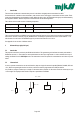
3.2 Format of a message 3.2.1 Format of the message sent by the master Note on the presentation of messages: Each box presents 1 data byte consisting of 8 bits, unless otherwise stated. Each message sent by the master possesses the following format: DevAddr 0 Function code n byte parameters (optional) KELLER:CRC16_H MODBUS:CRC16_L KELLER:CRC16_L MODBUS:CRC16_H • DevAddr: Address of the device. Address 0 is reserved for broadcasting. Addresses 1...249 can be used for bus mode.
3.3 Principle of message interchange 3.3.1 General rules • An address may only be allocated to one device connected to the bus. If two devices on the bus have the same address, both will respond, leading to a conflict. • Every data interchange is initiated by the master. This means that a device may only transmit data if requested to do so by the master. • A message consists of several bytes. These bytes are transmitted without any interruption. Maximal time between two bytes: 1.5ms @ 9600 baud (1.
3.3.2.2 Exception errors The message has been received correctly (no transmission error has occurred), but the transmitted function number and/or the parameters are invalid. The slave responds with an exception error, unless the message has been received in broadcasting mode.
4 MODBUS communication 4.1 MODBUS Communication Basics Mode: Coding System: Bits per Byte: Error Check Field: Baudrate: Frame Layout: > 3.