Quick Guide 1
Contents Daily Use Display Display Keys Contrast Setup Reset the System Function Keys Basic Setup; Pump Control 1 Signal List Configuration Step by Step: Operation of the Pumps Overview Screen for Pump Control 1 Screen Information: Start/Stop Levels Manual Operation Pump Data Basic Flowchart 2 4 5 5 6 6 7 10 10 13 14 15 16 16 18 20 22 23
Introduction Thank you for choosing the MJK Connect® or Mµ Connect® controller and monitoring unit. MJK Connect® and Mµ Connect® are easy to install, calibrate and put into operation. To get the full advantages of MJK Connect® and Mµ Connect® MJK recommends that future users read this manual to get familiar with all details concerning MJK Connect® and Mµ Connect®. The equipment should be treated and used as directed by MJK Automation A/S to ensure a stable operation and precise measurements.
Daily Use This is a Quick Guide to get started with your Connect®. The following examples in this section will show and explain how a Connect® is configured as pump controller for a wastewater pump station with 2 pumps. In Connect® the function “Pump Control 1” is used to control the pumps through the level in the pumping sump. The complete manual for Connect® and Mµ Connect® can be found on www.mjk.com.
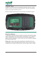
Display The 4 soft keys located below the display are used to navigate the menus during the daily operation of Connect®. Display Keys Numerical keys and soft keys are used for startup configuration and normal operation. Which of these is decided by the installed display firmware. The functions of the 4 soft keys are shown at the bottom of the display. The functions of the soft keys depends on which menu or function is currently active/shown.
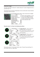
Contrast Setup Configure the display contrast by pressing the two outer soft keys simultaneously as shown with the red circles to the right. Then press the up/down arrows until you get the desired contrast. Save the changes by pressing the 2 outer soft keys simultaneously again. Reset the System It is possible to reset the system and refresh all system views and key combinations by pressing all four soft keys down simultaneously.
Function Keys The daily operation of Connect® and Mµ Connect® is done through the built-in function keys 1-9. The function keys (numerical keyboard) is also used for direct menu selection and typing names and texts. Each function key has pre-defined views and can be customized as needed. When selecting Index, an overview of the defined overview screens are created. Use this screen to make a quick switch to the selected screen. Function keys 1 to 3 have the following functions: Pump Control 1.
The function keys 4 to 9 have the following functions: Function key 4. Digital Inputs Shows status on all digital inputs. Function key 5. Digital Outputs Shows status on all digital outputs. Function key 6. Analog Inputs Shows status on all analog outputs. Function key 7. Communication Status Shows status on the communication. Is dependent on chosen communication module.
Function key 8. Alarm List Shows status on alarms. Function key 9. I/O Status Shows status on all inputs/outputs and analog limits, virtual analog outputs and logical flags (LF). Please note: Scroll with the up/down arrows to view more.
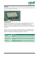
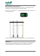
Basic Setup; Pump Control 1 This section will show and explain how a Connect® is configured as pump controller for a wastewater pump station with 2 pumps. The function “Pump Control 1” is used to control the pumps through the level in the pumping sump. The picture shows an example on 2-pump station with 2 submerged pumps. Signal List First step is to create a signal list to create a full overview of the signal from the pump controller to the pumps and from the pumps to the controller.
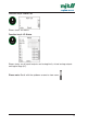
The list shows signals connected to the digital inputs in this example. Digital Signal Name Input Relay Function Delay Alarm / In use Alternation DI 1 Operation P1 NO 0 sec. In use In use DI 2 Operation P2 NO 5 sec. In use In use DI 4 Thermo alarm P1 NO 15 sec. Alarm DI 5 Thermo alarm P2 NO 15 sec. Alarm DI 3 DI 6 DI 7 Klixon P1 NO 0 sec. Alarm DI 8 Klixon P1 NO 0 sec.
Digital Input Signal Name Scaling Scaling 20 mA Unit Average AI 1 Level 0 300 Level 0 sec. AI 2 Power P1 0 10 Other Units 0 sec. AI 3 Power P2 0 10 Other Units 0 sec. AI 4 AI 5 AI 6 AI 7 Analog limits In use Not in use Signal Name Setpoint Delay Call AI 1 High In use High Level alarm XX 5 sec.
Configuration Next step is to configure the Connect® based on the shown signal list. In the function menu, choose Pump Control 1 and setup the specific menu items as described in the signal list. Go to Functions Menu and choose Pump Control 1, which contains the following items: • Number of Pumps: Number of pumps in the wasterwater pump station. • Measurement: The analog input on which the level transmitter is mounted on and scaling and signal name.
Step by Step: The display shows the setup like this Select Functions Menu Enter 2 and OK 14 Select Pump Control 1 Enter 2 and OK Select In use
Operation of the Pumps This section is based on the function “Pump Control 1” which is the most used Pump function. Function Key 1 is the screen used for the pump control and will typically be the same screen as in the Connect when working on the station. Please note that the pre-defined view described here can be customized to your needs. Select Function Key 1 for the daily use of the pump control 1. Overview display 1 is standard and located in the function section Pump Control 1.
Overview Screen for Pump Control 1 By pressing the right key below the display (P2), the display changes to a similar one for Pump 2. The key will then change name to P3 - P4, depending on how many pumps have been created in the function Pump Control 1. Navigate with the up/down arrows below Select. Arrow down will select the first/top line, another arrow down will select the second line, etc. Note: There can be discrepancies from this screen if lines have been added/ changed by the user.
Operation status of Pump Icon Description P1 Running Digital output when the pump is in use and the feedback signal is ok. P1 stopped Digital output when the pump has stopped and the feedback signal is missing. P1 error Digital output when the pump is in use and the feedback signal is missing. P1 Blocked Digital output when the pump is not in use.
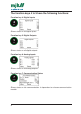
Start/Stop Levels How to change a start or stop level: Press Function key 1 to enter the overview screen for Pump Control 1. Use the arrow keys under the display to click down and select the line P1 Start. The last digit in the start level is now selected. Enter the new start level by using the numerical keyboard on the right. When the new value has been entered, save the value in Connect® with OK. You can now press the arrow down and change the stop level the same way as you changed the start level.
If you need to change the start/stop levels on the next pumps, press once more on the down arrow from Stop Level P1. Now P2 will be displayed in the lower right corner. Press the right soft key under P2 and the screen will change to Pump 2. Repeat the procedure as described above. By pressing the right soft key again, you will toggle between the number of pumps chosen for Pump Control 1. Note: It is a prerequisite that Pump Control has been set up and “Create Overview Screen” has been carried out.
Manual Operation How to start or stop a pump manually: Click the Function Key 1 to show the overview screen for Pump Control 1. Use the up/down arrows to select line 2, which shows the operation status. press “Operate” button to enter the Pump 1 menu. If you wish to start a pump, use the arrow keys to go down and select the Start Pump line and click OK. The pump is now stopped and will not start until the start level has been reached again and it is the pump’s turn in the alternation.
If you wish to stop a pump in use, use the up/down arrows to select Stop Pump and press OK. If you need to start or stop one of the next pumps, press once more on the down arrow from Stop Level P1. Now P2 will be displayed in the lower right corner. Press the right soft key below P2 and the screen will change to Pump 2. Repeat the procedure as described above. There are 4 views and icons of the Pump Status.
Pump Data The overview screen View Data provides a full overview of operation data for the pump. In this view, View Data is selected and an overview screen of pictures for the selected pump’s data is shown. You can choose between 3 different data screens. Totals Today Yesterday Text line Description Pump 1 This is the name of the function. You can change it to e.g. the pump number or any individual name. P1 Total/Today/ Yesterday Cnt. Count values (number of starts) for the selected pumps.
Basic Flowchart 23
EN 6.05 Connect QG 1210 Liability MJK Automation A/S are liable to the common rules of Danish law on product liability, however, the liability is reduced to coverage of our public liability insurance of products. To the extent where nothing else follows in lines of invariable rules of law, we are not liable for loss of profits and working deficits or other indirect losses. Changes As our products are developed continuously, we reserve the right to make any alterations without prior notice.