
Hardware Manual User Manual
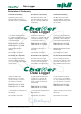

3. Specifications, Order Numbers and Accessories
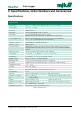
Specifications
Specifications
Digital inputs 4 pcs. 2 - 5 VDC (shortest interval 1x per count. 10 seconds)
Analog inputs 4 pcs. 0.1 - 2.5 VDC
Accuracy Better than ± 1%
Resolution 10 bit, input impedance min. 10 Kohm
Data inputs 1 pc. RS-485 Modbus input for max. 4 units.
Modbus RTU-mode, 9600 baud, 2-wire RS-485, master mode.
Power supply for I/O Built-in voltage regulated for sensors and other connected devices:
3.6 - 5 - 10 - 15 V DC (typically 100 mA @5 VDC)
Interface connector Internal USB 1.1, type mini B, female
Antenna socket MMCX, female
Data transmission
GSM/GPRS quad-band 850/900/1800/1900 MHz supporting TCP/IP protocol.
On-board SIM card holder, TCP/IP socket connection over GPRS and WWW
Internet
Memory/storage 30,000 measured values, time and date stamped
Log intervals 10 seconds, 1 – 10 minutes, 1, 2, 4, 8, 12 or 24 hours
Call intervals 10 minutes, 1, 2, 4, 8, 12 or 24 hours, 1 week
Supply voltage Built-in 3.6 VDC, 17 Ah lithium battery
Battery life time 5 years @1 measurement per day and 1 call per day
Installation In pipes with an inner diameter of Ø63 to Ø106 mm or wall mounting
Temperature range - 20 … 60 °C
Humidity Max. 95% relative
Clock Real-time clock with 1-second resolution, day clock
Encapsulation IP 67
Antenna Wall mounting: External (accessory), 0 dBd, 900/1800 MHz
Materials mounted in/
on:
Pipe: PC-ASA (top),
aluminum (base)
Wall: Glass reinforced polycarbonate (PC)
Weigth Pipe mounting: 1.8 kg Wall mounting: 0.7 kg
Dimensions mounted
in/on:
Pipe: Ø190 x Ø150 mm
(inner diameter Ø63 - Ø106 mm)
Wall: 156 x 144 x 83 mm (w x h x d)
Standards and norms EN 61000-6-2:2001, EN 61000-6-3:2001
Table 1. Specifications
3. Specifications, Order Numbers and Accessories
Data Logger
7