
Hardware Manual User Manual


List of Figures
Figure 1. Opening the Chatter Unit for Pipe Mounting 9
Figure 2. Terminal Blocks for Signal Inputs, Voltage Outputs and Serial Communication 10
Figure 3. Other Main Components on the Circuit Board 13
Figure 4. Secure Stud Bolts and Wedges with a Rubber Band 16
Figure 5. Center the Base 16
Figure 6. Screw by Hand 16
Figure 7. Tighten the Screws with a Spanner 17
Figure 8. Fasten the Security Wire 17
Figure 9. Immerse the Pressure Transmitter 18
Figure 10. Connect the Pressure Transmitter Cable 18
Figure 11. Mount the Padlock 19
Figure 12. Top Mounted and Secured Right and Wrong 19
Figure 13. Pipe Mounted Chatter Unit 21
Figure 14. Chatter Top Mounted Right and Wrong 22
Figure 15. Wall Mounted Chatter in Custom-designed Cabinet 23
Figure 16. Access to SIM Card - Wall Mounting 23
Figure 17. SIM Card Holder - Empty and Locked 25
Figure 18. SIM Card Holder - Empty and Open 25
Figure 19. SIM Card Correctly Inserted into the Grooves 26
Figure 20. SIM Card Secured in the Card Holder 26
Figure 21. Connection Example 1 - MJK Expert Transmitter 29
Figure 22. Connection Example 2 - Digital Input 30
Figure 23. On-Off Jumper from ”OFF” to ”ON” position 31
Figure 24. Mechanic Dimensions - Pipe Mounted 33
Figure 25. Mechanic Dimensions - Wall Mounted 33
Figure 26. Lengths and Datum 43
List of Tables
Table 1. Specifications 7
Table 2. Order Numbers 8
Table 3. Accessories 8
Table 4. Digital Inputs 10
Table 5. Analog Inputs 11
Table 6. Voltage Outputs for MJK-approved Equipment 11
Table 7. RS-485 Serial Data Communication 12
Table 8. Wedge Sizes 15
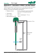
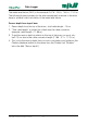
Appendix C. Calculation of WLD- and Ref. Datum
Data Logger
45