
Hardware Manual User Manual

Serial Data Communication for Modbus (5)
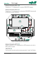
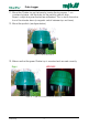
Chatter is equipped with RS-485 serial data communications. See position
“5” in Figure 2.
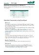
RS-485 Serial Data Communication for Modbus
Terminal Designation/function
A (RS485) Signal A
B (RS485) Signal B
GND (RS485) Ground
GND Ground
Table 7. RS-485 Serial Data Communication
Other Main Components on the Circuit Board
Battery (6)
The battery is located on top of the Chatter PCB (see Figure 3). Connec-
tion is through a connector placed in the middle of the circuit board (“Bat-
tery”, red and black wires).
Please note that the battery can be replaced without first setting the Chat-
ter unit in ”OFF” position.
See section 6. Gain Access to SIM Card and Battery and section 7.
Internal Installation in the Chatter Unit for gaining access to and chang-
ing the battery.
Jumper (7)
A jumper is placed right below the battery with two positions: ON and
OFF. In ON position the Chatter incl. pressure transmitter is powered (acti-
vated), and in OFF position it is disconnected (switched off).
Booster Capacitor (8)
The booster capacitor delivers current during data transmissions.
SIM Card (9)
The SIM card facilitate communication via the GSM/GPRS network.
See also the procedure for inserting/changing the SIM card in section
7. Internal Installation in the Chatter Unit on page 25.
Data Logger
12GB Chatter Hardware Manual 100416