
Hardware Manual User Manual


Analog Inputs (2)
Chatter
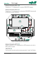
has four analog inputs each with a range of 0,1 - 2,5 VDC (see posi-
tion “2” on the drawing to the left).
Analog inputs
Terminal Designation/function
AI 1 0.1 - 2.5 VDC
AI 2 0.1 - 2.5 VDC
AI 3 0.1 - 2.5 VDC
AI 4 0.1 - 2.5 VDC
GND Common GND terminal for AI 1 - 4
Table 5. Analog Inputs
USB Connector (3)
Chatter is equipped with a USB socket for communication with for example a
laptop computer for configuration.
Voltage Outputs (4)
Chatter has three voltage outputs for MJK-approved equipment: one from
the factory programmable 5/10/15 VDC supply and two separate 3.6 VDC
outputs.
Voltage Outputs
Terminal Designation/function
+5/ 10/ 15 VDC Programmable, ON/OFF-controlled voltage supply (+5 VDC from factory)
GND Ground
3V6-A 3.6 volt (always ON)
GND Ground
3V6-B 3.6 volt (ON/OFF-controlled by the electronics during measurement)
GND Ground
Table 6. Voltage Outputs for MJK-approved Equipment
The outputs ”5/10/15” and ”3V6-B” are controlled in such a way that they are
activated during measurement. ”3V6-A” is connected directly to the battery
and is as such always active.
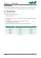
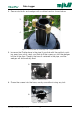
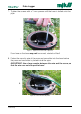
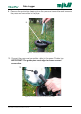
4. Electrical Connections
Data Logger
11