Data Logger Data Logger Hardware Installation and User Manual GB Chatter Hardware Manual 100416 1
Data Logger Declaration of Conformity Konformitetserklæring Declaration of Conformity Konformitätserklärung Vi, MJK Automation A/S, DK-2850 Nærum, påtager os det fulde ansvar for at produktet We, MJK Automation A/S, DK-2850 Nærum, declare under our sole responsibility that the product Wir, MJK Automation A/S, DK-2850 Nærum, erklären in alleiniger Verantwortung, dass das Produkt Data Logger som denne erklæring angår, er i overensstemmelse med følgende standard(er) eller andre normdokument(er).
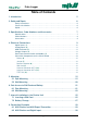
Data Logger Table of Contents 1. Introduction 5 2. Safety and Repair 6 Safery Instructions . . . . . . . . . . . . . . . . . . . . . . . . . . . . . . . . . . . . . . . . . . . . . . . . . . . 6 Physical installation. . . . . . . . . . . . . . . . . . . . . . . . . . . . . . . . . . . . . . . . . . . . . . . . . . . 6 Repair . . . . . . . . . . . . . . . . . . . . . . . . . . . .
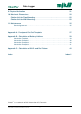
Data Logger 9. Physical Activation 31 10. Mechanic Dimensions 33 Chatter Unit for Pipe Mounting . . . . . . . . . . . . . . . . . . . . . . . . . . . . . . . . . . . . 33 Chatter Unit for Wall Mounting. . . . . . . . . . . . . . . . . . . . . . . . . . . . . . . . . . . . . 33 11. Maintenance 35 Service Agreement . . . . . . . . . . . . . . . . . . . . . . . . . . . . . . . . . . . . . . . . . . . . . . . . . . 35 Appendix A.
Data Logger 1. Introduction Thank you for choosing MJK Chatter™ Data Logger. We have done our best to design and produce a quality data logger to meet your requirements. Chatter is easy to install, calibrate and set into operation. To ensure the best result MJK recommends that the user reads this manual to become familiar with all features, functions and details of the Chatter data logger.
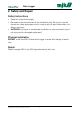
Data Logger 2. Safety and Repair Safery Instructions • Read this manual thoroughly • Be aware of the environment at the installation site. Be sure to use the necessary safety equipment and to comply with all applicable safety conditions and rules. • WARNING: Improper or inadequate installation or use may lead to physical injury and/or damaged equipment ! Physical installation DO NOT install the MJK Chatter data logger in areas with danger of explosion.
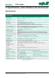
Data Logger 3. Specifications, Order Numbers and Accessories Specifications Specifications Digital inputs 4 pcs. 2 - 5 VDC (shortest interval 1x per count. 10 seconds) Analog inputs 4 pcs. 0.1 - 2.5 VDC Accuracy Better than ± 1% Resolution 10 bit, input impedance min. 10 Kohm Data inputs 1 pc. RS-485 Modbus input for max. 4 units. Modbus RTU-mode, 9600 baud, 2-wire RS-485, master mode. Power supply for I/O Built-in voltage regulated for sensors and other connected devices: 3.
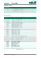
Data Logger Order Numbers Order Numbers 204105 Chatter™ GSM / GPRS for pipe mounting 204106 Chatter™ GSM/GPRS/GPS for pipe mounting 204110 Chatter™ GSM / GPRS for wall mounting 204111 Chatter™ GSM/GPRS/GPS for wall mounting Table 2. Order Numbers Accessories Accessories Antennas See data sheet GB 6.
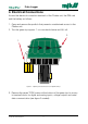
Data Logger 4. Electrical Connections Access the electrical connection terminals of the Chatter unit, the SIM card and the battery as follows: 1. Open and remove the padlock that prevents unauthorized access to the Chatter unit. 2. Turn the green top approx. 1 cm counterclockwise and lift it off. 2. 1. Figure 1. Opening the Chatter Unit for Pipe Mounting 3.
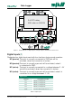
Data Logger ANT.3 ANT.2 3.6 VDC battery MJK order no. 550246 ANT.1 ON OFF TEST SW SIM card 5 GND GND B GND RS485 A GND 3V6-B 4 3V6-A GND AI 4 GND AI 3 AI 1 AI 2 USB Battery +5/ 10/ 15V 3 2 DI 4 GND DI 3 DI 1 DI 2 1 Figure 2.
Data Logger Analog Inputs (2) Chatter has four analog inputs each with a range of 0,1 - 2,5 VDC (see position “2” on the drawing to the left). Analog inputs Terminal Designation/function AI 1 0.1 - 2.5 VDC AI 2 0.1 - 2.5 VDC AI 3 0.1 - 2.5 VDC AI 4 0.1 - 2.5 VDC GND Common GND terminal for AI 1 - 4 Table 5. Analog Inputs USB Connector (3) Chatter is equipped with a USB socket for communication with for example a laptop computer for configuration.
Data Logger Serial Data Communication for Modbus (5) Chatter is equipped with RS-485 serial data communications. See position “5” in Figure 2. RS-485 Serial Data Communication for Modbus Terminal Designation/function A (RS485) Signal A B (RS485) Signal B GND (RS485) Ground GND Ground Table 7. RS-485 Serial Data Communication Other Main Components on the Circuit Board Battery (6) The battery is located on top of the Chatter PCB (see Figure 3).
Data Logger Antenna Connector ANT.1 (10) Connector no. 1 is designated for a standard GSM/GPRS antenna. Antenna Connector ANT.2 (11) Connector no. 2 is designated for an alternative GSM/GPRS antenna with an alternative modem installation. ANT.2 11 ANT.3 12 6 10 7 9 ON OFF 8 GND B RS485 A GND SIM card GND 3V6-B 3V6-A GND AI 4 TEST SW +5/ 10/ 15V USB 13 GND AI 3 AI 1 AI 2 DI 4 GND DI 3 DI 1 DI 2 Battery GND ANT.1 Figure 3.
Data Logger This page is left blank.
Data Logger 5. Mounting MJK Chatter data logger is supplied in two different mounting versions: one for pipe mounting and one for wall mounting (mounting on wall or cabinet). 5.1 Pipe Mounting Necessary tools and parts: • Wedge set to fit pipe diameter • Socket spanner, 7 mm 1. Activate the Chatter unit(s) as described in section 9. Physical Activation on page 31. 2. Re-assemble the Chatter unit(s) as described in section 6.2 Wall Mounting on page 23. 3.
Data Logger 4. Secure stud bolts and wedges with a rubber band as shown below. 3. 4. Figure 4. Secure Stud Bolts and Wedges with a Rubber Band 5. Immerse the Chatter base in the pipe (if possible with the padlock pointing away from public view), and then pull the screws up until the wedges buckle in the pipe. Thereby the base is centered in the pipe, and the wedges will automatically level. 5. Figure 5. Center the Base 6. Screw the screws into the base, one by one without using any tool: 6.
Data Logger 7. Tighten the screws with a 7 mm spanner until the base is bolted onto the pipe: 7. Figure 7. Tighten the Screws with a Spanner From here on the base may not be moved, rotated or lifted! 8. Fasten the security wire of the pressure transmitter into the base before the pressure transmitter is placed inside the pipe. IMPORTANT: Use a large washer between the wire and the screw, so that the wire can not escape the base! 8. Figure 8. Fasten the Security Wire 5.
Data Logger 9. Remove the protective sleeving from the pressure transmitter and immerse the pressure transmitter in the pipe. 9. Figure 9. Immerse the Pressure Transmitter 10. Connect the pressure transmitter cable to the green Chatter top. IMPORTANT: The guide pins must align to ensure correct connection. 10. Figure 10.
Data Logger 11. Mount the Chatter top on the base by turning the top approx. 1 cm counter-clockwise, until the holes for the security padlock align. Expect a slight drag over the last few millimeters. This is due to the activation of the intruder alarm (a magnetic switch between top and base). 12. Mount the padlock (see figure below). 12. Figure 11. Mount the Padlock 13. Make sure that the green Chatter top is mounted and secured correctly: Right WRONG! Figure 12.
Data Logger 5.2 Wall Mounting 1. Mount the cabinet on the wall. 2. Connect the pressure transmitter(s) according to the example in section 8.1 MJK Chatter and MJK Expert Transmitter on page 29. 3. Connect the relevant in- and outputs. 4. Aktivate the Chatter unit(s) as described in section 9. Physical Activation on page 31. 5. Close the Chatter unit(s) as described in section 6.2 Wall Mounting on page 23.
Data Logger 6. Gain Access to SIM Card and Battery To change SIM card or battery in a Chatter unit, you must gain access to the unit’s circuit board. 6.1 Pipe Mounting 1. Open and remove the padlock that prevents unauthorized access to the Chatter unit. 2. Turn the green top approx. 1 cm counterclockwise (but do not lift it off!) 3. Leave the top on for about two minutes and then lift it off. This is to ensure a valid measurement and to allow time for sending an alarm to the server. 4.
Data Logger 9. Re-connect the pressure transmitter connector by turning the union clockwise. 10. Immerse the pressure transmitter into the pipe, and make sure that the cable and the security wire hang freely inside the pipe to ensure reliable measurements. 11. Mount the Chatter top at the base by turning the top approx. 1 cm counter-clockwise, until the holes for the security padlock align. Expect a slight drag over the last few millimeters.
Data Logger 6.2 Wall Mounting 1. Locate the Chatter unit: Figure 15. Wall Mounted Chatter in Custom-designed Cabinet 2. Loosen the four screws in the top cover to open the Chatter unit: Figure 16. Access to SIM Card - Wall Mounting 3. Insert SIM card or change battery as described in section 7. Internal Installation in the Chatter Unit on page 25. 4. Re-assemble the Chatter unit. IMPORTANT: Make sure that the leads do not get stuck or become squeezed between the cabinet and the cover. 5.
Data Logger This page is left blank.
Data Logger 7. Internal Installation in the Chatter Unit 7.1 Inserting a SIM Card 1. Open the Chatter unit to gain accesss to the circuit board and the SIM card holder as described in section 6. Gain Access to SIM Card and Battery on page 21. 2. Open the SIM card holder by applying light pressure on the upper part (the lid) and at the same time dragging it towards the edge of the circuit board (here: to the right as indicated by the arrow): Figure 17.
Data Logger 3. Carefully insert the SIM card into the grooves that hold the card, and finally push it to the end stop. IMPORTANT: The SIM card must align with the grooves all the way down. Likewise the SIM card’s right, cut-off corner must point upwards and to the left (see arrow): Figure 19. SIM Card Correctly Inserted into the Grooves 4.
Data Logger 7.2 Battery Change 1. Open the Chatter unit to gain accesss to the circuit board and the battery as described in section 6. Gain Access to SIM Card and Battery on page 21. 2. Carefully push the battery sidewards to free it from the cable strap that holds the battery. Alternatively you can cut the cable strap (this requires, however, that you use a new strap for the new battery). 3. Disconnect the battery leads (red and black) from the Chatter circuit board by pulling out the “Batt” plug. 4.
Data Logger This page is left blank.
MJK Expert™ 7070 Niveau Transmitter har de samme specifikationer som 7060-transmitteren, men har derudover en meget lille ydre diameter og er fremstillet i 316L syrefast, rustfrit stål. Transmitteren er specielt udviklet til niveaumålinger i boringer, brønde og drikkevandsbeholdere. Data Logger Transmitterne leveres med piezo-resistivt målesy8. Connection Examples stem og hhv.
Data Logger 8.2 MJK Chatter and Digital Input ANT.2 ANT.3 ANT.1 ON OFF GND GND B RS485 A GND SIM card GND 3V6-B GND 3V6-A USB +5/ 10/ 15V AI 4 GND AI 3 AI 1 AI 2 DI 4 GND DI 3 DI 1 DI 2 Battery 2-5 VDC Figure 22. Connection Example 2 - Digital Input In this example DI1 and DI2 are connected ”passive”, and DI4 is connected ”active”.
Data Logger 9. Physical Activation The Chatter unit is activated physically by moving the jumper shown on page 12 and in the figures below from position ”OFF” to position ”ON”. Figure 23. On-Off Jumper from ”OFF” to ”ON” position 9.
Data Logger This page is left blank.
Data Logger 10. Mechanic Dimensions Chatter Unit for Pipe Mounting 190 mm 190 150 mm 150 101 mm 101 Indre rørdiameter Inner pipe diameter Ø 63 - 106 mm Ø63 - Ø106 Figure 24. Mechanic Dimensions - Pipe Mounted Chatter Unit for Wall Mounting 156 144 83 Figure 25. Mechanic Dimensions - Wall Mounted 10.
Data Logger This page is left blank.
Data Logger 11. Maintenance The MJK Chatter Data Logger requires no maintenance. Service Agreement A service agreement guaranties the equipment’s long term reliability and accuracy. Contact one of MJK’s national sales- or service representatives to make a service agreement with regular service visits. 11.
Data Logger This page is left blank.
Data Logger Appendix A. Frontpanel Cut-Out Template Appendix A. Frontpanel Cut-Out Template Cut-out area Up The dotted lines indicate the Frontpanel front panel contour and measures 155 x 145 mm.
Data Logger This page is left blank.
Data Logger Appendix B. Calculation of Battery Lifetime The battery in the MJK Chatter unit is of the lithium-trionyl-ion-trotyl type which is characterized by a high energy density, a low self-discharge, and a long lifetime. The energy density is 17 Ah nominal and guarantied 15 Ah (15.000 mAh). Depending on the use of the Chatter unit you can estimate the battery lifetime. The Chatter will, depending on the setup, execute one control call every 25th. hour (if a shorter interval has not been selected).
Data Logger Calculation Example 1 Chatter basic consumption per day (fixed) = 1.0 No. of logs per day @sensor consump.=2mA 1 x 0.1 = 0.1 No. of logs per day @sensor consump. =4mA x 0.2 = No. of event logs per day @sensor consump.=2mA x 0.1 = No. of event logs per day @sensor consump. =4mA x 0.2 = No. of calls per day 1 x 3 = 3.0 No. of alarm calls per day 0.01 x 3 = 0.03 Consumption per day (total): 4.
Data Logger Calculation Example 3 Chatter basic consumption per day (fixed) = No. of logs per day @sensor consump.=2mA 24 x 0.1 = No. of logs per day @sensor consump. =4mA x 0.2 = No. of event logs per day @sensor consump.=2mA 180 x 0.1 = No. of event logs per day @sensor consump. =4mA x 0.2 = No. of calls per day 2 x 3 = No. of alarm calls per day x 3 = Consumption per day (total): Battery lifetime in days: Battery lifetime in months: Battery lifetime in years: Appendix B.
Data Logger This page is left blank.
Data Logger Appendix C. Calculation of WLD- and Ref. Datum The following examples illustrate how you can calculate the water level datum (WLD) in relation to the cable length and the reference datum of a bore. Example: A bore has the following characteristics: • Reference datum: 34.76 m (the level at which the Chatter base rests on the pipe/bore head) • Cable length: 25.0 m • Sensor depth: 24.9 m (cable length - 10 cm) • Measurement from DB: 7.
Data Logger The water level datum (WLD) in this example: 34.76 - 24.9 + 7.65 => 17.51 m The following figures/numbers for the bore are required as entries to the data base to achieve a valid calculation of the water level datum. Sensor depth from top of bore 1. Sensor depth from the top of the bore = total cable length – 10cm. 2. “Total cable length” is printed on a label near the cable connector (example: cable length = 11.86 m). 3.
Data Logger List of Figures Figure 1. Figure 2. Figure 3. Figure 4. Figure 5. Figure 6. Figure 7. Figure 8. Figure 9. Figure 10. Figure 11. Figure 12. Figure 13. Figure 14. Figure 15. Figure 16. Figure 17. Figure 18. Figure 19. Figure 20. Figure 21. Figure 22. Figure 23. Figure 24. Figure 25. Figure 26.
Data Logger This page is left blank.
Data Logger Index I A accesssories . . . . . . . . . . . . . . . . . . . accuracy . . . . . . . . . . . . . . . . . . . . . . activation . . . . . . . . . . . . . . . . . . . . . alarm . . . . . . . . . . . . . . . . . . . . . . . . analog inputs . . . . . . . . . . . . . . . . 7, antenna connector . . . . . . . . . . . 7, antennas . . . . . . . . . . . . . . . . . . . . . . inputs . . . . . . . . . . . . . . . . . . . . . . . . 7 interface connector . . . . . . . . . . . . . . 7 intruder . . .
Data Logger service agreement . . . . . . . . . . . . . . SIM card . . . . . . . . . . . . 7, 12, 21, specifications . . . . . . . . . . . . . . . . . . . strap . . . . . . . . . . . . . . . . . . . . . . . . stud bolts . . . . . . . . . . . . . . . . . . . . switch . . . . . . . . . . . . . . . . . . . . . . . 35 25 7 27 16 19 T TCP/IP . . . . . . . . . . . . . . . . . . . . . . . temperature range . . . . . . . . . . . . . . . template . . . . . . . . . . . . . . . . . . . . .
Data Logger This page is left blank.
Data Logger Liability MJK Automation A/S are liable to the common rules of Danish law on product liability, however, the liability is reduced to coverage of our public liability insurance of products. To the extent where nothing else follows in lines of invariable rules of law, we are not liable for loss of profits and working deficits or other indirect losses. Changes As our products are developed continuously, we reserve the right to make any alterations without prior notice.