
User guide
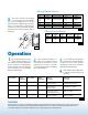
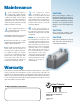

FIGURE 1
FIGURE 2
T
Mb
Mv
F
Operation
Liquid Hot Liquid Cold
Gas Hot Liquid Cold
Condensing Gas Hot Liquid Cold
Liquid or Gas Hot Vaporizing Liquid Cold
Condensers
REFRIGERATION: STEAM TO LIQUID
Refrig. In: F1
Refrig. Out: F4
Liquid In: F3
Liquid Out: F2
Evaporators
Refrig. In: F4
Refrig. Out: F1
Liquid In: F2
Liquid Out: F3
Evaporators
Refrig. In: ......... F4
Refrig. Out: ...... F1
Liquid In:............ F2
Liquid Out: ......... F3
Condensers
Steam In: F1
Condensate Out: F4
Liquid In: F3
Liquid Out: F2
STEAM TO LIQUID
Condensers
Steam In: ......... F1
Condensate Out: F4
Liquid In:............ F3
Liquid Out: ......... F2
Model T (lbs) F (lbs) M
b
(in-lbs) M
v
(in-lbs)
400 3327 1798.4 (-1348.8) 327.5 1504.6
410
411 5552.6 1798.4 (-1348.8) 540 1504.6
412
415 5552.6 2158.1 (-1663.5) 540 3407.5
422 24952.8 6069.6 (-4720.8) 6550 8912.7
433 Consult Factory Consult Factory
Model T (lbs) F (lbs) M
b
(in-lbs) M
v
(in-lbs)
400 200 100 20 200
410
411 280 130 27 300
412
Start both fluids gradually
at the same time.
Start cold fluid
first then hot fluid.
Start hot fluid first then
slowly start cold fluid.
Avoid temperature shock.
Start hot fluid
first then cold fluid.
Shut down both fluids
gradually at the same time.
Shut down hot fluid
gradually then cold fluid.
Shut down cold fluid
first then hot fluid.
Shut down cold fluid
first then hot fluid.
Type of Fluid Relative Type of Fluid Relative Start-Up Shut-Down
Temperature Temperature Procedure Procedure
Condensers
REFRIGERATION:
Refrig. In: ......... F1
Refrig. Out: ...... F4
Liquid In:............ F3
Liquid Out: ......... F2
TABLE 2
TABLE 4
TABLE 3
1.
Be sure the entire system is clean
before starting operation to pre-
vent plugging of passages with debris.
The use of strainers or settling tanks in
pipelines leading to the heat exchanger
is recommended. The recommended
strainer size is 20-24 mesh.
Start operating gradually. See
Table 4 for suggested start-up
and shut-down procedures for most
applications. If in doubt, consult the
nearest ITT Heat Transfer representative
for specific instructions.
Do not operate the heat exchanger
under pressure and/or temperature
conditions in excess of the specified
design limits shown on the nameplate
attached to the heat exchanger.
Drain all fluids when shutting down
to eliminate possible freezing and
corroding.
2. 3.
4.
A heat exchanger is a pressure vessel designed for operation at certain specific limits of pressure and temperature. The cooling or process system,
which includes the heat exchanger, must be safeguarded with safety valves and controls so that these heat exchanger design conditions are not
exceeded. All operating personnel should be made aware of these specific design pressures and temperatures.
CAUTION:
Liquid Hot Liquid Cold
Gas Hot Liquid Cold
Condensing Gas Hot Liquid Cold
Liquid or Gas Hot Vaporizing Liquid Cold
Condensers
REFRIGERATION: STEAM TO LIQUID
Refrig. In: F1
Refrig. Out: F4
Liquid In: F3
Liquid Out: F2
Evaporators
Refrig. In: F4
Refrig. Out: F1
Liquid In: F2
Liquid Out: F3
Evaporators
Refrig. In: ......... F4
Refrig. Out: ...... F1
Liquid In:............ F2
Liquid Out: ......... F3
Condensers
Steam In: F1
Condensate Out: F4
Liquid In: F3
Liquid Out: F2
STEAM TO LIQUID
Condensers
Steam In: ......... F1
Condensate Out: F4
Liquid In:............ F3
Liquid Out: ......... F2
Model T (lbs) F (lbs) M
b
(in-lbs) M
v
(in-lbs)
400 3327 1798.4 (-1348.8) 327.5 1504.6
410
411 5552.6 1798.4 (-1348.8) 540 1504.6
412
415 5552.6 2158.1 (-1663.5) 540 3407.5
422 24952.8 6069.6 (-4720.8) 6550 8912.7
433 Consult Factory Consult Factory
Model T (lbs) F (lbs) M
b
(in-lbs) M
v
(in-lbs)
400 200 100 20 200
410
411 280 130 27 300
412
Start both fluids gradually
at the same time.
Start cold fluid
first then hot fluid.
Start hot fluid first then
slowly start cold fluid.
Avoid temperature shock.
Start hot fluid
first then cold fluid.
Shut down both fluids
gradually at the same time.
Shut down hot fluid
gradually then cold fluid.
Shut down cold fluid
first then hot fluid.
Shut down cold fluid
first then hot fluid.
Type of Fluid Relative Type of Fluid Relative Start-Up Shut-Down
Temperature Temperature Procedure Procedure
Condensers
REFRIGERATION:
Refrig. In: ......... F1
Refrig. Out: ...... F4
Liquid In:............ F3
Liquid Out: ......... F2
TABLE 2
TABLE 4
TABLE 3
435 psig Standard Design
Liquid Hot Liquid Cold
Gas Hot Liquid Cold
Condensing Gas Hot Liquid Cold
Liquid or Gas Hot Vaporizing Liquid Cold
Condensers
REFRIGERATION: STEAM TO LIQUID
Refrig. In: F1
Refrig. Out: F4
Liquid In: F3
Liquid Out: F2
Evaporators
Refrig. In: F4
Refrig. Out: F1
Liquid In: F2
Liquid Out: F3
Evaporators
Refrig. In: ......... F4
Refrig. Out: ...... F1
Liquid In:............ F2
Liquid Out: ......... F3
Condensers
Steam In: F1
Condensate Out: F4
Liquid In: F3
Liquid Out: F2
STEAM TO LIQUID
Condensers
Steam In: ......... F1
Condensate Out: F4
Liquid In:............ F3
Liquid Out: ......... F2
Model T (lbs) F (lbs) M
b
(in-lbs) M
v
(in-lbs)
400 3327 1798.4 (-1348.8) 327.5 1504.6
410
411 5552.6 1798.4 (-1348.8) 540 1504.6
412
415 5552.6 2158.1 (-1663.5) 540 3407.5
422 24952.8 6069.6 (-4720.8) 6550 8912.7
433 Consult Factory Consult Factory
Model T (lbs) F (lbs) M
b
(in-lbs) M
v
(in-lbs)
400 200 100 20 200
410
411 280 130 27 300
412
Start both fluids gradually
at the same time.
Start cold fluid
first then hot fluid.
Start hot fluid first then
slowly start cold fluid.
Avoid temperature shock.
Start hot fluid
first then cold fluid.
Shut down both fluids
gradually at the same time.
Shut down hot fluid
gradually then cold fluid.
Shut down cold fluid
first then hot fluid.
Shut down cold fluid
first then hot fluid.
Type of Fluid Relative Type of Fluid Relative Start-Up Shut-Down
Temperature Temperature Procedure Procedure
Condensers
REFRIGERATION:
Refrig. In: ......... F1
Refrig. Out: ...... F4
Liquid In:............ F3
Liquid Out: ......... F2
TABLE 2
TABLE 4
TABLE 3
150 psig Pressure Design
8.
The nozzle connections are designed
for normal torque force and damage
may occur if over tightened. The use of pipe
sealant materials compatible with the system
fluids is recommended for threaded type
connections. Connection load limits should be
observed and are shown in Figure 2, Table 2,
and Table 3.