
User guide

Upon receipt of the exchanger, inspect for shipping
damage, especially to the connections. If damage is
extensive, notify the carrier immediately. Finally, check the
heat exchanger against proper drawings and spec sheets to
make sure everything is as expected.
Before piping up, inspect all openings in the
heat exchanger for foreign material. Remove all plugs
and shipping covers immediately prior to installing.
Make sure it is thoroughly cleaned to remove all preservation
materials, if any were used, unless the material is soluble in
the system fluid.
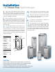
For single phase fluids, the heat exchanger can be
mounted in any orientation that is convenient and
should be piped in a counter current, parallel flow
arrangement. For two phase fluids, the heat exchanger
should be mounted vertically and piped as shown in
Figure 1 and Table 1. Connections may be either on the front
or back of the exchanger.
Provide air vent valves for the heat exchanger so that it
can be purged to prevent or relieve vapor or gas binding.
Install proper relief valves and temperature alarms
to make sure the heat exchanger is not subject to
conditions beyond the intended design.
Do not weld or braze brackets or attachments
directly to body of heat exchanger.
For soldering type connections, braze with minimum
45% silver solder and at maximum 1200° F. For
welded type connections use TIG or MIG welding. Avoid
overheating. A wet cloth or rag should be placed around the
base of the connection. A Nitrogen purge should be used to
avoid internal oxidation. Braze or weld with exchanger in
the vertical position.
Installation
of ITT Brazed Plate Heat Exchangers
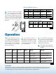
FIGURE 1
FIGURE 2
T
Mb
Mv
F
Liquid Hot Liquid Cold
Gas Hot Liquid Cold
Condensing Gas Hot Liquid Cold
Liquid or Gas Hot Vaporizing Liquid Cold
Condensers
REFRIGERATION: STEAM TO LIQUID
Refrig. In: F1
Refrig. Out: F4
Liquid In: F3
Liquid Out: F2
Evaporators
Refrig. In: F4
Refrig. Out: F1
Liquid In: F2
Liquid Out: F3
Evaporators
Refrig. In: ......... F4
Refrig. Out: ...... F1
Liquid In:............ F2
Liquid Out: ......... F3
Condensers
Steam In: F1
Condensate Out: F4
Liquid In: F3
Liquid Out: F2
STEAM TO LIQUID
Condensers
Steam In: ......... F1
Condensate Out: F4
Liquid In:............ F3
Liquid Out: ......... F2
Model T (lbs) F (lbs) M
b
(in-lbs) M
v
(in-lbs)
400 3327 1798.4 (-1348.8) 327.5 1504.6
410
411 5552.6 1798.4 (-1348.8) 540 1504.6
412
415 5552.6 2158.1 (-1663.5) 540 3407.5
422 24952.8 6069.6 (-4720.8) 6550 8912.7
433 Consult Factory Consult Factory
Model T (lbs) F (lbs) M
b
(in-lbs) M
v
(in-lbs)
400 200 100 20 200
410
411 280 130 27 300
412
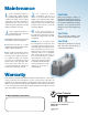
Start both fluids gradually
at the same time.
Start cold fluid
first then hot fluid.
Start hot fluid first then
slowly start cold fluid.
Avoid temperature shock.
Start hot fluid
first then cold fluid.
Shut down both fluids
gradually at the same time.
Shut down hot fluid
gradually then cold fluid.
Shut down cold fluid
first then hot fluid.
Shut down cold fluid
first then hot fluid.
Type of Fluid Relative Type of Fluid Relative Start-Up Shut-Down
Temperature Temperature Procedure Procedure
Condensers
REFRIGERATION:
Refrig. In: ......... F1
Refrig. Out: ...... F4
Liquid In:............ F3
Liquid Out: ......... F2
TABLE 2
TABLE 4
TABLE 3
1.
2.
3.
4.
5.
6.
7.
Many Heat exchangers circulate fluids which are irritating or dangerous to the human system.
These fluids could cause problems if bolted or threaded joints are not maintained in a leak tight
condition at operating pressures, temperatures, and no flow, ambient conditions.
Even if fluids are not irritating or dangerous, a leak could cause a slippery situation on the floor below.
Since one fluid in the heat exchanger is at a higher temperature, any leaks may cause burns.
CAUTION:
TABLE 1