
User Manual


50
M795GB0503
Data Transmitter 795
SW ver. 830434
Dimensions: 185 x 240 x 115 mm (h × w × d)
Power supply: 230 / 115 V AC or 12 / 24 V DC
Emergency power: Built-in accumulator for monitoring of power supply and emergency communication.
Kapacitet for ca. 3 nødopkald pr. opladning á 12 timer.
Power consumption: 15 VA (Approx.)
Temperature range: - 20 … + 60 °C
Material, housing: Polystyrol
Material, lid: Makrolon
Enclosure: IP 65
Ur: Real time clock with built-in battery backup
Kommunikation
Telephone / fax: Hayes compatible, auto dial, auto answer, 2400 / 4800 baud
GSM / GPRS: 900 / 1800 MHz GSM / GPRS modem
UHF: Data radio via RS 232 port
APL / owned lines: RS 485 for owned lines (multidrop)
Accuracy: < ± ½ % for analogue inputs
CE: EN50081-1, EN50082-1
Appendix
A Appendix
A1 Technical specifications
A4 Dimensions
A2 Number of signals available
Number of possible signals on a standard Data Transmitter 795
I/O Limit relays Counters Time counters Alarms
Analoge indgange 4 8 8 8 8
Digitale indgange 8/12/16 8/12/16 8/12/16 8/12/16
Digitale udgange 8/4/0
Antal i alt 20 8 16/20/24 16/20/24 16/20/24
Alle værdier overføres som i dag, i går og totalværdier.
Analogue inputs: 0/4 - 20 mA or 0 - 1 V DC. Input voltage = 50 Ω.
Digital inputs: 8 / 12 / 16 DI, passive with common negative pole, max. 24 V DC. (Optocoupler with 10 kΩ serial resistor)
Trig voltage: < 1 V DC = Off, > 10 V DC = On, pulse length > 100 ms.
Digital outputs: 0 / 4 / 8 DO, voltage free relay contacts, max. 1 A v. 24 V DC / 0,5 A v. 48 V AC.
Digital I/O: Total 16 DI + DO
Data communication: 2 x ports (RS 485 with item no. 204570 built-in)
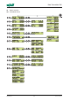
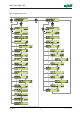
A3 Inputs and outputs