
User Manual


3
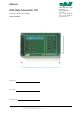
M795GB0503
Data Transmitter 795
SW ver. 830434
Contents
1 Introduction .......................................... 5
1.1 Versions ........................................................5
1.2 Communications protocols ........................... 5
1.3 MJK-Link™ .................................................. 6
1.4 About this manual ........................................ 6
1.5 Safety instructions ........................................6
1.6 Product identification .................................... 6
1.6.1 Standard versions 7
1.6.2 Versions with built-in options 7
2 Mechanical mounting .......................... 8
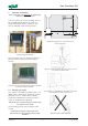
2.1 Mounting on a wall ....................................... 8
3 Electrical mounting .............................. 9
3.1 Power supply................................................9
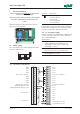
3.2 In- and output signals 9
3.2.1 I/O terminals, 8 DI/8 DO/4 AI 9
3.2.2 I/O terminals, 12 DI/4 DO/4 AI 10
3.2.3 I/O terminals, 16 DI/4 AI 10
3.3 Connection examples ................................. 11
3.3.1 Digital inputs 11
3.3.2 Digital outputs 11
3.3.3 Analogue inputs 11
3.3 Connection of Pump Controller 704 ...........12
3.4 Connection of communications ports .........12
3.4.1 Communications port 12
3.4.2 Built-in modem 12
4 The front panel ................................... 13
4.1 Display and keys 13
4.2 Menu structure ...........................................13
5 Functional menus ............................... 14
5.1.1 F0 - Program version, time and date 14
5.1.2 F0 - Interlock, operation or alarm signal 14
5.1.3 F0 - Internal flag, operation
or alarm signal 14
5.1.4 F0 - Limits, high/low 14
5.1.5 F0 - Digital inputs,
operation or alarm signal 14
5.2 F1 - Digital inputs on/off ............................. 14
5.3.1 F2 - Digital outputs on/off 14
5.3.2 F2 - Internal flag on/off 14
5.4 F3 - Limits - High/Low ................................ 15
5.5 F4 - Analogue input value # ........................ 15
5.5.1 F5 - Analogue input scaling 15
5.5.2 F5 - Analogue input on
Pump Controller 704 15
5.6 F6 - Counter for inputs ...............................15
5.7 F7 - Counter for time ..................................15
5.8 F8 - Alarm / Alarm number ........................16
5.9.1 F9.1 - Stormflow volume 16
5.9.2 F9.2 - Stormflow calculation 16
5.10 F# - Modem/Line status ............................. 16
5.11 F* - Communication status ......................... 16
6 Programming of main functions........ 17
6.1 Select language ..........................................17
6.2 Set time and date ....................................... 17
6.3 Automatic change between
summer time and winter time .....................17
6.4 Access code enabled/disabled ................... 17
6.4.1 Enter password 17
6.5 Calculation of average values on
analogue inputs ..........................................17
6.6 Data logging interval ................................... 17
6.7 Tone / pulse dialing ..................................... 17
6.8 Alarm call on power failure.......................... 17
6.9 Number of incoming rings before answer ...18
6.10 ID. no. for the Data Transmitter ...................18
6.11 Automatic reset of alarms ...........................18
6.11.1 Call on automatic alarm reset 18
6.12 Start time for operational reports ................ 18
6.13 795 telephone number ............................... 18
6.14 SMSC telephone number ........................... 18
6.15 RS485 function...........................................18
6.15.1 Master ID number 18
7 Programming of analogue inputs ..... 19
7.1 Select analogue input .................................19
7.2 0 - 20 or 4 - 20 mA input ............................19
7.3 Scaling at 0 / 4 mA ..................................... 19
7.4 Scaling at 20 mA ........................................19
7.5 Monitoring of high limit ............................... 19
7.5.1 Set high limit 19
7.5.2 High limit operation / alarm 19
7.5.3 Dialout on high limit 19
7.5.4 Signal delay for exceeding high limit 19
7.6 Monitoring of low limit ................................. 19
7.6.1 Set low limit 20
7.6.2 Low limit operation / alarm 20
7.6.3 Dialout on high limit 20
7.6.4 Signal delay for exceeding low limit 20
7.7 Divisor ........................................................20
8 Programming of digital inputs ........... 20
8.1 Select a digital input ................................... 20
8.2 NO or NC ...................................................20
8.3 Operational or alarm input ..........................20
8.3.1 Dialout on alarm 20
8.4 Signal delay ................................................ 20
9 Programming of digital outputs ........ 21
9.1 Select a digital output .................................21
9.2 NO or NC ...................................................21
9.3 Time controlled output................................ 21
9.4 ON time ...................................................... 21
9.4.1 Time before start 21