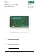
Manual MJK Data Transmitter 795 Valid from software version 830434 COMLI PROTOCOL Station ID: 795 Type: 795 Serial no: M795GB0503 As our products are developed continuously, we reserve the right to make any changes without prior notice. MJK Automation A/S Byageren 7 DK-2850 Nærum Denmark Tel: +45 45 56 06 56 Fax: +45 45 56 06 46 www.mjk.
Data Transmitter 795 Konformitetserklæring Declaration of Conformity Konformitätserklärung Vi, MJK Automation A/S, DK-2850 Nærum, påtager os det fulde ansvar for at produktet We, MJK Automation A/S, DK-2850 Nærum, declare under our sole responsibility that the product Wir, MJK Automation A/S, DK-2850 Nærum, erklären in alleiniger Verantwortung, dass das Produkt MJK Data Transmitter 795 som denne erklæring angår, er i overensstemmelse med følgende standard(er) eller andre normdokument(er).
Data Transmitter 795 Contents 1 Introduction .......................................... 5 6 1.1 1.2 1.3 1.4 1.5 1.6 1.6.1 1.6.2 Versions ........................................................ 5 Communications protocols ........................... 5 MJK-Link™ .................................................. 6 About this manual ........................................ 6 Safety instructions ........................................ 6 Product identification ....................................
Data Transmitter 795 10 Programming of logical functions ..... 21 15 Programming of 702 ComTroller ....... 29 10.1 Select the output to receive the result of the logical function .................................. 21 10.2 Select logical function ................................. 21 10.2.1 Select signals for the logical function 21 10.2.2 Operational or alarm signal on internal flag 22 10.2.3 Dialout when alarm signal on internal flag 22 10.2.4 Signal delay on internal flag 22 15.1 Select 702 .........
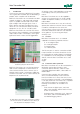
Data Transmitter 795 1 Introduction Thank you for choosing an MJK Data Transmitter 795. A great effort has been put into developing a product, which complies with all demands. All settings, alarms and logged data can be read in the display, from easy to use functionnal menus. MJK Data Transmitter 795 can be supplied in versions that communicates via a built-in GSM modem or telephone modem, or in versions for radio modem.
Data Transmitter 795 1.3 MJK-Link™ The Windows based program MJK-Link™ can be applied to monitor one or several MJK Data Transmitter 795. Via a PC with modem it is possible with MJK-Link™ to read values, modify setpoints and read datalogger for e.g. storm flow values. All settings in Data Transmitter 795 can be implemented via MJK-Link™. Explosion hazardous areas MJK Data Transmitter 795 is not approved for use in explosion hazardous areas.
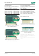
Data Transmitter 795 1.6.1 Standard versions This manual covers the following standard versions with Comli protocol: 1.6.2 Versions with built-in options The following type options can be built into Data Transmitter 795: Item no.: In- and outputs: Communication: Varenr.
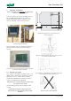
Data Transmitter 795 2 Mechanical mounting Data Transmitter 795 must not be mounted in explosion hazardous areas! Data Transmitter 795 is IP65 enclosed, and can be mounted outdoors directly on a wall or a railing, eventually by means of MJK rain roof 200115 and MJK universal fitting 200205. Dimensional drawing for mounting screws. See also page 51. MJK rain roof 200115 mounted on pole with MJK universal bracket 200205.
Data Transmitter 795 3 Electrical mounting Data Transmitter 795 must not be mounted in explosion hazardous areas! Terminal: N L + Data Transmitter 795 must not be connected to the power supply before all connections are made. Remove the terminal lid and the front panel to gain acces to all terminals.
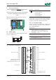
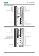
Data Transmitter 795 3.2.2 I/O terminals, 12 DI/4 DO/4 AI DI 9 + DI 10 + DI 11 + DI 12 + DI 9/10/11/12 common DO 1 DO 2 DO 3 DO 4 DO 1/2/3/4 common Screen for RS232 to 704 Signal ground for RS232 to 704 DI 1 + DI 2 + DI 3 + DI 4 + DI 1/2/3/4 common DI 5 + DI 6 + DI 7 + DI 8 + DI 5/6/7/8 common AI 1 + AI 1 AI 2 + AI 2 AI 3 + AI 3 AI 4 + AI 4 Rx for RS232 to 704 Tx for RS232 to 704 24 V DC out + 24 V DC out - 3.2.
Data Transmitter 795 3.3 Connection examples 3.3.1 Digital inputs The digital inputs are passive, i.e. they need to be supplied from an external power source or from the terminals marked '24 V'. 3.3.3 Analogue inputs The analog inputs are passive. i.e. they must be supplied from an external power source or from the terminals marked '24 V'. Note, that the inputs has common negative in groups of 4 inputs. Every input have its own plus and negative terminal.
Data Transmitter 795 3.3 Connection of Pump Controller 704 Only the RS232 port on the plug-in terminals of the Data Transmitter can be used for connecting a MJK Pump Controller 704. A screened, twisted pair cable must be used, and it should be connected as shown below: The shield must not be connected to the Pump Controller 704. Max. cable length is 15 metres. DO NOT CONNECT THE SHIELD IN THIS END! 3.4 Connection of communications ports (Only item no. 204520 / 21 / 22.) 3.4.
Data Transmitter 795 4 The front panel Display 2 x 24 digit backlit alphanumerical display for indication of user menus and measuring values. 4.1 Display and keys Numerical keys The keys 0-9, #, are used to enter telephone numbers, delays, analogue scaling etc. * 4.2 ESC. key This key is used to go back to the previous menu, or to cancel a selection. Press this key 2 or 3 times to revert to functional indication. MENU key This key is used to switch between main menus and submenus.
Data Transmitter 795 5 Functional menus 5.2 F1 - Digital inputs on/off Menu F1 indicates if the digital inputs are set ON or OFF. Up to 8 inputs are shown simultaneously. 5.1.1 F0 - Program version, time and date Menu F0 displays date og and time. Moreover, it will display the current communications protocol and program version. If there are more than 8 inputs, the remaining inputs will be displayed by pressing one of the arrow keys: 5.1.
Data Transmitter 795 5.4 F3 - Limits - High/Low Menu F3 indicates if high and low limit is ON or OFF for the analogue inputs. The first four digits indicate if the high limit setting is exceeded and the last four digits indicate if the low limit setting is exceeded: 5.5.
Data Transmitter 795 5.8 F8 - Alarm / Alarm number Menu F8 indicate if the last 9 alarms are ON or OFF: 5.9.2 F9.2 - Stormflow calculation Whenever a stormflow occur, the flow is displayed as m3/h in menu F9-2: Each time a new alarm is activated, it will be recorded as alarm no. 1 and all other recorded alarms will move down one place and alarm 9 will be deleted. When the alarm for one input has been ON one time it must be set to OFF before a new alarm from the same input is accepted as an alarm. 5.
Data Transmitter 795 6 Programming of main functions 6.1 Select language 6.5 Calculation of average values on analogue inputs The value of an analogue input is recorded every second, and every 5 minutes the values is logged. If averaging of the analogue values are selected, an average of the analogue value over the last 5 minutes will be calculated and logged. Select the desired language with the arrow keys and confirm with ENTER. 6.
Data Transmitter 795 6.9 Number of incoming rings before answer Set the number of rings (1 to 5) before Data Transmitter 795 answer the call. 6.13 795 telephone number Enter the telephone number that the Data Transmitter is connected to. The number is used as ID no. in connection with transmission of SMS alarms through landlines. Use the arrow keys or numerical keys 1 to 5 to select and confirm with ENTER. Use the numerical keys and confirm with ENTER. 6.
Data Transmitter 795 7 Programming of analogue inputs 7.1 Select analogue input 7.5.1 Set high limit Set the upper limit value that should cause a recording in the operational or alarm log - see also section 13, "Operational or alarm signal". Select the desired analogue input with the arrow keys and confirm with ENTER. 7.2 In case the input are not scaled, 20 mA on the analogue input will correspond to 9999. 0 - 20 or 4 - 20 mA input Use the arrow keys or numerical keys and confirm with ENTER.
Data Transmitter 795 8 Programming of digital inputs 7.6.1 Set low limit Set the lower limit value that should cause a recording in the operational or alarm log - see also section 13, "Operational or alarm signal". 8.1 Select a digital input In case the input are not scaled, 0 / 4 mA on the analogue input will correspond to 0. Select the desired digital input with the arrow keys and confirm with ENTER. 8.
Data Transmitter 795 9 Programming of digital outputs 9.1 Select a digital output 10 Programming of logical functions This menu gives the possibility to program simple logical functions like AND, OR, and SET/RESET based on different digital signals in both Data Transmitter 795 and the Pump Controller 704 (if connected). Select the desired digital output with the arrow keys and confirm with ENTER. 9.
Data Transmitter 795 11 Programming of interlock With this function it will be possible for two Data Transmitters to send command to each other. E.g. one Data Transmitter can control a digital output on another Data Transmitter. 1: Select the upper input signal with the arrow keys and confirm with ENTER. 2: After that, select the lower input signal and confirm with ENTER. Please note, that DO1 and DO2 may be used by the pump controller function - see also section 12.
Data Transmitter 795 11.4 Interlock active / inactive Select if the previously chosen Data Transmitter (substation) should be interlocked. Use arrow keys and confirm with ENTER. 11.4.1 Start of interlock Select the signal initiating an interlock on the selected Data Transmitter (substation): The following signals are available: - Only one call attemt will be made. In case the same signal are selected as both start condition and stop condition, the stop condition will be when the digital signal goes OFF.
Data Transmitter 795 Please note, that only a Master Data Transmitter can directly remote control other Data Transmitters belonging to other clusters. Use the numeric keys and confirm with ENTER. Eks.: Data Transmitter ID 001 is supposed to remote control Data Transmitter ID 003: Enter the ID number "003" into Data Transmitter 001. 11.4.
Data Transmitter 795 12 Programming of Pump Controller(s) 12.2.2 Start level for pump no. 1 Select the desired start level for pump no. 1: 12.1 704 connected Select if a MJK Pump Controller 704 are connected to the Data Transmitter: Use the arrow keys and confirm with ENTER. Use the arrow keys and confirm with ENTER. 12.2.2 Stop level for pump no. 1 Select the desired stop level for the pump(s). 12.
Data Transmitter 795 13 Telephone list for alarms (Not valid for versions with radio modem.) The message can be different for the individual telephone numbers. Pager messages will be displayed in the pager together with a code for the alarm type that have caused the call. 13.1 Telephone number 1-9 This menu contain a list where up to 9 telephone numbers can be entered. An example: When digital input no.
Data Transmitter 795 14 13.2.3 Enter SMS message If the current telephone number type is selected as an SMS type, enter an SMS message/code of up to 8 digits: Programming of stormflow calculation 14.1 Stormflow calculation Data Transmitter 795 can calculate the flow of an overrun via a digital input an an analogue input. MJK 795 Use the numerical keys and confirm with ENTER.
Data Transmitter 795 If these Q(h) values are entered in this menu, the resulting Q(h) curve will be as shown below, and the Data Transmitter will calculate the flow according to this curve: 14.2.3 Number of Q(h) points In this menu the number of Q(h) points that are desired for the piece by piece linearization of the flow calculation. The number of Q(h) points can be set from 1 and 9, as the zero point value will be provided to be 0 m3/h. Use the arow keys and confirm with ENTER. 14.2.
Data Transmitter 795 15 Programming of 702 ComTroller If one or more 702 ComTrollers is connected to the Data Transmitter as multidrop units on the RS485 port, they can all be programmed via the Data Transmitter's keyboard and display. (The Data Transmitter must be the Master in the cluster.) 15.1 Select 702 Enter the ID number for the desired 702 ComTroller: Use the arow keys and confirm with ENTER.
Data Transmitter 795 16 Alarms 16.1 Operational or alarm signal The digital inputs can be set to be either a operational or alarm signals. 16.3 Reset of alarms When an alarm signal becomes active, it will be visible in menu F8 (see section 5.8). An operational signal defines a non-critical condition, e.g. a signal that only need to be recorded in the operational log. It would typically be a signal indicating whether a pump is running or not.
Data Transmitter 795 17 Factory settings Main functions: Settings: Main functions: Language English Autochange summer/winter time No Access code No Averaging of analog inputs No Datalogging interval 00:30 (30 sek.) Tone/Pulse dialing Tone Alarm call on power failure No Analogue inputs: 0-20mA/4-20mA Scaling @ 0/4 mA Scaling @ 20 mA High limit yes/no High limit value High limit operational/alarm Signal delay (sec.
Data Transmitter 795 Storm flow calculation: In use Yes/No Zero point Level signal No of Q(h) points Q(h) point no. 1 Q(h) point no. 2 Q(h) point no. 3 Q(h) point no. 4 Q(h) point no. 5 Q(h) point no. 6 Q(h) point no. 7 Q(h) point no. 8 Q(h) point no. 9 M795GB0503 Setting: Level: 10 Level: 10 Level: 10 Level: 10 Level: 10 Level: 10 Level: 10 Level: 10 Level: 10 No DI1 704 level 9 ; Flow (m3/h) : 1.11 ; Flow (m3/h) : 2.22 ; Flow (m3/h) : 3.33 ; Flow (m3/h) : 4.44 ; Flow (m3/h) : 5.55 ; Flow (m3/h) : 6.
Data Transmitter 795 18 g Signal lists PUMP STATION NO: MJK 795 ID NO: PUMP CONTROLLER TYPE: NAME: SERIAL NO. MJK 795: CONTROLLER SERIAL NO.: TELEPHONE NO.: DATE: SENSOR SERIAL NO.: DATA TRANSMITTER MJK 795 MAIN FUNCTIONS CODE: ANALOG AVERAGING DIAL METHOD DIALOUT ON VOLTAGE ERROR DATA LOGGING INTERVAL MM:SS YES NO TONE PULSE YES NO.
Data Transmitter 795 DIGITAL INPUTS DI 1-8 DI 1-12 DI 1-16 SIGNAL NAME: SIGNAL ALARM NO NC SIGNAL DELAYED MIN:SEC DIAL VIA TEL.: TIME FIXED NO NC DELAY BEFORE START MIN:SEC ON-TIME DI 1 DI 2 DI 3 DI 4 DI 5 DI 6 DI 7 DI 8 DI 9 DI 10 DI 11 DI 12 DI 13 DI 14 DI 15 DI 16 DIGITAL OUTPUTS (@ 8 or 12 DI) SIGNAL NAME: MIN:SEC DO 1 DO 2 DO 3 DO 4 DO 5 DO 6 DO 7 DO 8 DO 9 DO 10 DO 11 DO 12 M795GB0503 34 SW ver.
Data Transmitter 795 INTERLOCK START INTERLOCK STOP INTERLOCK RECEIVERS OUTPUT NO. RECEIVERS TEL NO.: PUMP CONTROLLER MJK 704 YES NO CONNECTED ALARM CALL OUTPUT 1 ALARM CALL OUTPUT 2 ALARM CALL OUTPUT 3 ALARM CALL OUTPUT 4 ALARM CALL ON SYSTEM ERROR TELEPHONE NUMBERS FOR ALARM CALLS TELEPHONE NUMBER PC: TEL.: PAGER: SMS: PAGE / SMS MESSAGE: NO. 1: NO. 2: NO. 3: NO. 4: NO. 5: NO. 6: NO. 7: NO. 8: NO. 9: M795GB0503 35 SW ver.
Data Transmitter 795 STORM FLOW CALCULATION IN USE: YES: NO: ZERO POINT: LEVEL MEASUREMENT: NO. OF Q(h) POINTS: 3 LEVEL: FLOW: (M /h) HEIGHT VALUE NO. 1: HEIGHT VALUE NO. 2: HEIGHT VALUE NO. 3: HEIGHT VALUE NO. 4: HEIGHT VALUE NO. 5: HEIGHT VALUE NO. 6: HEIGHT VALUE NO. 7: HEIGHT VALUE NO. 8: HEIGHT VALUE NO.
Data Transmitter 795 19 Register list ONLINE VALUES: I/O NO.
Data Transmitter 795 ONLINE VALUES: I/O NO.: DESCRIPTION: Internal flag 1 116 117 140 read/write read/write read/reset Internal flag Internal flag Internal flag Internal flag Internal flag Internal flag Internal flag Test alarm 141 142 143 144 145 146 147 150 read/reset read/reset read/reset read/reset read/reset read/reset read/reset read/reset 2 3 4 5 6 7 8 ONLINE VALUES: REG. NO.
Data Transmitter 795 COUNTERS, 'TOTAL' DI 1 pulse counter DI 2 pulse counter DI 3 pulse counter DI 4 pulse counter DI 5 pulse counter DI 6 pulse counter DI 7 pulse counter DI 8 pulse counter DI 9 pulse counter DI 10 pulse counter DI 11 pulse counter DI 12 pulse counter DI 13 pulse counter DI 14 pulse counter DI 15 pulse counter DI 16 pulse counter DI 1 time counter DI 2 time counter DI 3 time counter DI 4 time counter DI 5 time counter DI 6 time counter DI 7 time counter Di 8 time counter DI 9 time counter
Data Transmitter 795 COUNTERS, 'TODAY' DI 1 pulse counter DI 2 pulse counter DI 3 pulse counter DI 4 pulse counter DI 5 pulse counter DI 6 pulse counter DI 7 pulse counter DI 8 pulse counter DI 9 pulse counter DI 10 pulse counter DI 11 pulse counter DI 12 pulse counter DI 13 pulse counter DI 14 pulse counter DI 15 pulse counter DI 16 pulse counter DI 1 time counter DI 2 time counter DI 3 time counter DI 4 time counter DI 5 time counter DI 6 time counter DI 7 time counter DI 8 time counter DI 9 time counter
Data Transmitter 795 COUNTERS, 'YESTERDAY' REG. NO.
Data Transmitter 795 LOG, 24 h á 5 min: Analogue Analogue Analogue Analogue Analogue Analogue Analogue Analogue 704 level 704 level input input input input input input input input 1 1 2 2 3 3 4 4 REG. NO.: VALUE: 288 575 576 863 864 1151 1152 1439 1440 1727 DESCRIPTION: The The The The The The The The The The lowest logged value. oldest logged value. lowest logged value. oldest logged value. lowest logged value. oldest logged value. lowest logged value. oldest logged value. lowest logged value.
Data Transmitter 795 M795GB0503 43 SW ver.
Data Transmitter 795 20 Menu structure 20.1 Functional menus M795GB0503 44 SW ver.
Data Transmitter 795 20.2 Programming menus M795GB0503 45 SW ver.
Data Transmitter 795 M795GB0503 46 SW ver.
Data Transmitter 795 M795GB0503 47 SW ver.
Data Transmitter 795 M795GB0503 48 SW ver.
Data Transmitter 795 M795GB0503 49 SW ver.
Appendix A Appendix A1 Technical specifications Data Transmitter 795 Dimensions: 185 x 240 x 115 mm (h × w × d) Power supply: 230 / 115 V AC or 12 / 24 V DC Emergency power: Built-in accumulator for monitoring of power supply and emergency communication. Kapacitet for ca. 3 nødopkald pr. opladning á 12 timer. Power consumption: 15 VA (Approx.
Data Transmitter 795 B Appendix Appendix See also separate documentation for GSM/GPRS option. B1 Maintenance In case the function 'Alarm call at power failure' is acticvated, it is recommended to exchange the built-in accumulator yearly. Beyond this, MJK Data Transmitter 795 require no particular maintenance. B2.6 Total reset This code give access to a TOTAL RESET. Enter F 0 and 2 0 4 5.
Data Transmitter 795 B4 SMSC telephone numbers The SMS messages from Datatransmitter 795 must be dialed to an SMS central server on one of the following numbers: Denmark: (+45) 90 13 12 01 The Netherlands: (+31) 653 14 14 14 Norway: (+47) 90 00 21 98 Portugal: (+35) 19 62 11 3000 Sveden: (+46) 7 40 93 00 00 Germany: (+49) 172 227 80 20 B5 Spare parts Item no.
M795DK0303 53 SW ver.
Data Transmitter 795 M795GB0503 54 SW ver.