Manual MJK Comtroller 702 Effective for software version 83XXXX COMLI PROTOKOL Unit ID: Serial no.: M702GB/0110 Rev. 111001 As our products are developed continuously, we reserve the right to make any change in dimensions and specifications.
CE - CERTIFICATE OF CONFORMITY This product complies with the requirements concerning electromagnetic compatibility (EMC) stipulated in Council directive no. 89/336/EEC of 3rd May 1989, altered at directive no. 92/31/EEC, on the approximation of the laws of the Member States relating to electromagnetic compatibility. We declare that the product complies to the values stipulated in EN 50081-1 and EN 50082-1. M702GB/0110 Rev.
ComTroller 702 Contents 1 General ................................................. 5 6 Digital inputs ..................................... 12 1.2 MJK-Link™ ................................................... 5 2 Operation .............................................. 6 3 Menus ................................................... 8 3.1 Digital input # .............................................. 12 Alarm / in use .............................................. 12 Signal delayed ...............
ComTroller 702 13 Alarms ................................................. 16 15 Electrical connection .......................... 18 13.1 13.2 13.3 13.4 13.5 13.6 13.7 13.8 Operational or alarm signal .......................... 16 Alarm calls .................................................. 16 Reset of alarms ........................................... 16 Special factory codes .................................. 16 Access code ...............................................
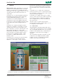
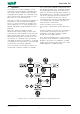
ComTroller 702 1 General MJK Comtroller 702 is developed for control and surveillance of small pumping stations and water borings. Comtroller 702 is a complete unit with inand outputs, CPU, data logger, real time clock and communications port for data transmission on owned lines. Comtroller 702 is an advanced product based on the experience from the thousands of monitoring systems delivered during the past 15 years.
ComTroller 702 2 702's on the same multidrop communications line. The desired Comtroller 702 is selected by entering the corresponding ID-number on the Data Transmitter 795, after which the selected Comtroller can be operated exactly as if it were a Data Transmitter 795. At the same time the Data Transmitter 795 contains a surveillance function that calls the Comtrollers one by one over an adjustable interval. If a Comtroller does not respond, the Data transmitter will send a system alarm.
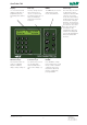
ComTroller 702 Display ESC.-key MENU Arrow keys 2 x 24 character backlit display for indication of programming menus, measuring values alarms etc. This key changes back to the previous menu or cancels a selection. By pressing the ESC.-key 2-3 times you will always return to the functional indication. The MENU key are used to switch between main menus and submenus. The arrow keys are used for altering the current setting.
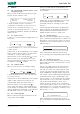
ComTroller 702 3 Menus The first two fields indicate if the high limits are exceeded and the last two show if the low limits are exceeded. 3.1 F0 - Unit type/ID, software version, clock and protocol type Menu F0 show the MJK unit type, protocol type, program version and date / time. MJK 702 : 3 16:07:29 LIMITS HIGH/LOW ON : OFF: COMLI 830802 24/10/01 1234561 2 In above example, the Data Transmitter is connected to a Comtroller 702 with unit ID no. 3.
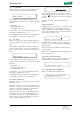
ComTroller 702 3.7 F6 - Counter Menu F6 shows how many times a digital input or an analog high or low limit has been set ON. COUNTER DI # RESET: ENTER ALARM NO 123456789 A flashing field indicates that the alarm is ON, an empty field indicates that the alarm is OFF, and a steady field indicates that the alarm has been reset. 257 Every single input / high and low limit has its own counter. Use the arrow keys to change the readout between: All alarms in the list will be reset by pressing ENTER.
ComTroller 702 4 that would be caused by very short voltage failures. Main functions 4.1 Choose language The desired language is chosen using the arrow keys - confirm with ENTER. This function is only available if the Comtroller is supplied from an external 12 V DC source with battery backup. 4.2 Set time and date The time and date can be set using the arrow keys or the numerical keys. Confirm the changes with ENTER or press MENU if no changes are desired.
ComTroller 702 5 Analog inputs 5.10 Low limit yes / no Select if exceeding the low limit setting on the analog input should be registered. 5.1 Analog input # Select the input to be set by pressing 1. Confirm with ENTER. Use the arrow keys to select and confirm with ENTER. 5.2 Input no 1 0 - 20 / 4 / 20 mA Select if the signal range for the analog input should be either 0 - 20 mA or 4 - 20 mA. 5.11 Set low limit Set the low limit that the analog input should exceed before the event is registered.
ComTroller 702 6 7 Digital inputs Digital outputs 6.1 Digital input # Use the arrow keys or enter 1 to 4 to select the input to be programmed. 7.1 Digital output # Use the arrow keys or enter 1 to 4 to select the output to be programmed. 6.2 Alarm / in use See section 13.1 for a description between "Limit alarm" and "In use". 7.2 NO / NC Select the relay function to normally open (NO) or normally closed (NC).
ComTroller 702 8 Interlock When interlocking two MJK Comtroller 702's they will communicate with one another. In this way one data transmitter can control a digital output remotely on the other. 8.1 Interlock in use yes/no Select whether the interlock function is to be used or not. Use the arrow keys to select and confirm with ENTER. 8.5 Receivers telephone number Enter the ID number of the remote Comtroller and confirm with ENTER or start press ENTER to correct a number already keyed in. 8.
ComTroller 702 10 Telephone list for alarms E.g. a datatransmitter with telephone number 455660656 where digital input 5 has an active alarm input; will give the following alarm message in the PS: (This section applies is only 10.1 Telephone number 1-9 In this menu up to 9 telephone numbers are keyed in which will be dialed chronologically at an alarm situation.
ComTroller 702 11 Programming of storm flow calculation 12 11.1 Stormflow calculation Comtroller 702 can be applied for calculation of storm flow by means of one digital and analogue input. Generally Comtroller 702 is applied to a level meter with measuring range adapted to the pump controller. This measuring range is normally considerably higher, than what is necessary for flow measurement, generally 10m for the pump controller and 10-20cm for flow calculation.
ComTroller 702 13 Alarms indicating the status. The symbol flashes until the alarm is registered which makes the symbol permanently lit. The symbol stays lit until the alarm signal is no longer active, then the signal disapears and the stop time will show instead of the start time. 13.1 Operational or alarm signal The digital signals can be chosen as either operational or alarm signals. A operational signal can be defined as non-critical, i.e. a signal, that one want to be registered.
ComTroller 702 14 Other information 14.1 Specifications Supply: 230 V AC / 12 V DC. Fuse: 63 mA T built-in Analog inputs: 2 AI, 0-20 / 4-20 mA or 0 - 1 V DC Digital inputs: 4 DI, optocoupler with10 kΩ serial resistor Digital outputs: 4 DO, relays, maxs. 48 V AC, 1A Consumption: Approx. 5 VA Temp.
ComTroller 702 15 Electrical connection 15.5 Software upgrade If a software upgrade becomes necessary, it is possible to perform the upgrade yourself. The software is loaded into an EPROM. Do the following to change the EEPROM:: Al connections are shown on the front panel. 15.1 Digital inputs The digital inputs (DI 1-4) has optocouplers with 10 kΩ serial resistors. The inputs can be configured individually to normally open (NO) or normally closed (NC).
ComTroller 702 M702GB/0110 Rev.
ComTroller 702 16 Factory settings Main functions: Setting: Language English Access code No Change between summer and winter time No Analog input averaging No Data logging interval 00:30 (30 sek.) Tone/Pulse dialing Tone Alarm - call by telephone No Rings before answer 1 ID-nr. for Comtroller Set via switches on the front Automatic reset of alarms No 702 phone number SMSC phone number Master or Slave Slave Analog inputs: Analog input 1: Analog input 2: 0-20mA/4-20mA 4-20 mA 4-20 mA Min. scaling 0 00 Max.
ComTroller 702 Pump Controller: Pump control activated Yes / No Telephone list: Telephone no 1 Telephone no 2 Telephone no 3 Telephone no 4 Telephone no 5 Telephone no 6 Telephone no 7 Telephone no 8 Telephone no 9 Storm flow calculation: In use Yes / No Zero level Level measurement Number of points Q/H point no 1 Q/H point no 2 Q/H point no 3 Q/H point no 4 Q/H point no 5 Q/H point no 6 Q/H point no 7 Q/H point no 8 Q/H point no 9 Combi alarms: Combi alarm 1 Combi alarm 2 Combi alarm 3 Combi alarm 4 Combi