Instruction Manual Laing Thermotech ACT-4 wireless Potable Hot Water Recirculation Kit
Table of Contents Table of Contents Introduction and Safety................................................................................................ 2 Introduction............................................................................................................... 2 Safety.......................................................................................................................... 2 Safety terminology and symbols..................................................................
Introduction and Safety Introduction and Safety Introduction Purpose of this manual The purpose of this manual is to provide necessary information for: • Installation • Operation • Maintenance CAUTION: Read this manual carefully before installing and using the product. Improper use of the product can cause personal injury and damage to property, and may void the warranty. NOTICE: Save this manual for future reference, and keep it readily available at the location of the unit.
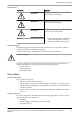
Introduction and Safety Hazard levels Hazard level NOTICE: Indication DANGER: A hazardous situation which, if not avoided, will result in death or serious injury WARNING: A hazardous situation which, if not avoided, could result in death or serious injury CAUTION: A hazardous situation which, if not avoided, could result in minor or moderate injury • A potential situation which, if not avoided, could result in undesirable conditions • A practice not related to personal injury Hazard categories Haza
Introduction and Safety • • • • • Protective gloves Gas mask Hearing protection First-aid kit Safety devices NOTICE: Never operate a unit unless safety devices are installed. Also see specific information about safety devices in other chapters of this manual. Electrical connections Electrical connections must be made by certified electricians in compliance with all international, national, state, and local regulations.
Introduction and Safety • Clean up all spills in accordance with safety and environmental procedures. • Report all environmental emissions to the appropriate authorities. WARNING: Radiation Hazard. Do NOT send the product to Xylem if it has been exposed to any nuclear radiation. Electrical installation For electrical installation recycling requirements, consult your local electric utility. Recycling guidelines Always follow local laws and regulations regarding recycling.
Product Description Product Description General description The ACT-4 wireless is a potable hot water recirculation kit for use in new and retrofit domestic hot water systems. The kit helps to: • Improve comfort through instant hot water • Save energy • Conserve water Parts included in kit • Pump with a built-in timer • 6 ft (1.8 m) power cord • Under-sink mixing valve with transmitter/receiver • Two 1.
Product Description WARNING: Do NOT exceed the maximum working pressure of the pump. This information is listed on the nameplate of the pump. WARNING: California Proposition 65 warning! This product contains chemicals known to the state of California to cause cancer and birth defects or other reproductive harm.
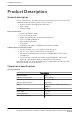
Product Description 5 6 7 4 8 9 1 3 10 2 1. 2. 3. 4. 5. 6. 7. 8. 9. 10.
Installation Installation Preinstallation CAUTION: All work must be performed by qualified personnel trained in the proper application, installation, and maintenance of plumbing, steam and electrical equipment or systems in accordance with all applicable codes and regulations. The pump and valve as received in this kit are factory paired and wirelessly communicate water temperature and pump status with each other. Before installation of the pump and valve, complete the following: • Shut off water supply.
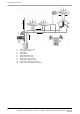
Installation Recommended installation 1 2 8 7 3 4 5 6 1. 2. 3.
Installation 4. 5. 6. 7. 8. 3/4” NPT male adapter, if required 3/4” NPT isolation valve Hot water source Hot water Flexible supply line Install the pump 1. Remove the motor and timer unit, O-ring, and insert from the pump housing. Set these items aside. 1 2 3 1. 2. 3. 2. Pump housing Pump o-ring Pump insert Connect the union end of the pump housing to the 3/4" NPT male inlet of the hot water source, or male adapter and isolation valve connected to the hot water source.
Installation 5. Orient the pump so that the timer is accessible. The timer should never be positioned in any orientation above the pump housing. 6. Make sure that the screw ring that attaches the motor to the pump is securely hand tightened. Do not attempt to further rotate the pump timer or the pump may be damaged. Over-tightening the pump screw ring can cause damage to the pump. Do not use pipe compound or plumber's putty on the screw ring. 7.
Installation 1. Prepare the installation site, which is the faucet/tap farthest from the hot water source. 2. Close the hot and cold water riser shutoff valves and open the hot and cold water faucets/taps to relieve the water pressure. Close the water faucets/ taps. In some older homes, the riser shutoff valves may be difficult to shut off completely. If so, turn off the water at the main water inlet valve to the house. 3.
Installation 7. Open the faucet/tap and hot and cold water riser shutoff valves to purge any air entrained in the valve or hoses and to insure there are no leaks at any connections. 8. Remove the locking screw from the battery compartment cover on the valve. Insert the batteries in their proper orientation into the compartment on the valve. Be sure to match the positive (+) and negative (-) ends of the batteries with the corresponding polarity symbols on the bottom of the housing.
Commissioning, Startup, Operation, and Shutdown Commissioning, Startup, Operation, and Shutdown Thermostat controlled operation The valve and pump are ready to communicate with each other out of the box. The pump comes with an adjustable temperature feature. This feature is controlled by the thermostat dial just above the timer housing on the body of the pump and may be set to activate between 86°F (30°C) and 95°F (35°C).
Commissioning, Startup, Operation, and Shutdown 16 1. Open the timer cover with a small flat head screwdriver. Verify that current time setting is correct. If not, rotate the dial clockwise until the correct time is aligned with the pointer at the top (12 o'clock position) of the dial. 2. Automatic Operation: Pull the tabs out on the timer for the desired operating time. For example, if the desired operating time is 9:00 AM to 11:00 AM, pull out all tabs from 9 through 11.
Commissioning, Startup, Operation, and Shutdown 1 1. Pull tabs out for desired time The timer can be set for multiple operating periods of time, in 1/2 hour increments. 3. Slide the switch bar to the clock symbol. Optional Push-Button / Signal Repeater The pump and valve as received in this kit are factory paired and wirelessly communicate water temperature and pump status with each other.
Commissioning, Startup, Operation, and Shutdown Push-Button Operation Follow this procedure when you add the push-button device to your system and pair it with your ACT4 wireless pump and valve: 1. Begin the pairing process by opening the timer cover on the pump and performing the following sequence with the pump timer switch: a) b) c) d) Slide the switch from the “ON” position to the “OFF” position and wait two (2) seconds. Slide the switch to the “ON” position and wait two (2) seconds.
Maintenance Maintenance Valve and pump inspection Periodically inspect the valve or pump for signs of leakage or corrosion. WARNING: Risk for property damage, serious personal injury or death. You must replace the valve or pump if corrosion or leakage is found. Pairing after pump or valve replacement If either the pump or the valve is replaced, device pairing is required. To pair the devices, follow this procedure: 1. Power up the valve by inserting the batteries.
Maintenance Return to service after shutdown of two weeks or more You may choose to turn the system off (slide the pump timer switch to the “OFF” position) as there is no need to maintain hot water in the supply line when no one is home. Before turning the system back on, follow these instructions: 20 1. Open the faucets/taps at the sink where the system is installed. Keep them open until all air is purged and the water flows smoothly. 2.
Troubleshooting Troubleshooting LED codes Pump LED sequence code Explanation No light Pump is off — no power Steady light on LED Pump is running or on stand-by One short and one long flash Low input voltage to pump Two short and one long flash Communication is lost between pump and valve Three short and one long flash Pump is overheated Four short and one long flash Pump is overloaded Five short and one long flash Blocked rotor inside pump Six short and one long flash Low battery voltage a
Troubleshooting Symptom Cause Remedy Pump is noisy Air in the system Turn off the ecocirc pump. Turn on the hot and cold faucets/taps until all air is purged from the system. Foreign matter in the rotor cavity Unplug pump and shut off water supply. Open faucets/taps and drain water from the piping. Loosen the screw ring to separate motor from the pump housing and check for foreign matter. Hot water is not instantly available at all faucets/taps Rotor does not seat properly.
Troubleshooting Symptom Cause Remedy Pump is overheated Hot water source is generating too much heat. Adjust temperature setting on hot water source. Ambient temperature is too hot. Make sure the pump and hot water source are properly ventilated to allow cooling. Communication is lost between pump and valve Pump is overloaded. See possible causes and remedies below. Batteries are dead/Low battery voltage. Replace batteries. Incorrect battery orientation. Verify correct battery orientation.
Xylem |’zīləm| 1) The tissue in plants that brings water upward from the roots 2) A leading global water technology company We're 12,000 people unified in a common purpose: creating innovative solutions to meet our world's water needs. Developing new technologies that will improve the way water is used, conserved, and re-used in the future is central to our work.