INSTRUCTION MANUAL 19-001-351R2 INSTALLER: PLEASE LEAVE THIS MANUAL FOR THE OWNER’S USE.
Acknowledgements All materials ©2013 by Flowtronex, A Xylem company. Flowtronex® is a registered trademark of Flowtronex a Xylem Company. All rights reserved. No parts of this work may be reproduced in any form or by any means - graphic, electronic, or mechanical, including photocopying, recording, taping, or information storage and retrieval systems - without the written permission of the publisher.
TABLE OF CONTENTS ACKNOWLEDGEMENTS ......................................... 2 ACKNOWLEDGEMENTS ......................................... 2 SETUP MENU .......................................................... 14 USER SETUP .................................................. 15 INTRODUCTION ....................................................... 6 Set/Sync HMI-PLC Date/Time ............................ 15 Lamp Test ........................................................... 15 HMI OVERVIEW ..............
TABLE OF FIGURES Figure 1: Basic Operation Figure 2: Enhanced Key Pad Figure 3: Basic Screen Layout Figure 4: Log in Screen Figure 5: Operation Menu Figure 6: Trends Screen Figure 7: Configure Period Figure 8: Flow Totals, Overview Figure 9: Flow Totals, Daily Flows Figure 10: Flow Totals, Weekly Flows Figure 11: Flow Totals Monthly Flows Figure 12: Flow Totals, Yearly Flows Figure 13: Animated Pump Status Figure 14: Individual Pump Stats Figure 15: Booster Monitoring Screen Figure 16: ALS Monitoring Screen
WARRANTY INFORMATION Company warrants title to the product(s) and, except as noted below with respect to items not of Company’s Manufacturer, also warrants the product(s) on date on shipment to Purchaser, to be of the kind and quality described herein, and free of defects in workmanship and material.
Introduction CAUTION: Equipment Damage Hazard To Clean the equipment: This manual is written for end users and is an TM introduction to the Xylem-Flowtronex® PACE HMI (Human Machine Interface). The HMI is a browserbased system which allows the user to interact with the settings and reports of the pumping system. This manual only covers the HMI aspect of the system. Please see the Silent Storm VFD Pumping System Instruction Manual for any questions not related to the HMI.
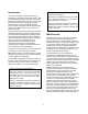
Touch-Screen Panel Operation This Flowtronex PACE HMI device manual describes the operation of the touch-panel display, located on the enclosure door of the control unit of the pumping station. • Use a stylus to tap the buttons or fields when using the touch-screen panel. • Use the Enhanced Key Pad to enter text or numbers in blank fields. Tap and hold the stylus in a blank field to open the Enhanced Key Pad pop up screen.
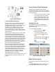
navigate to other key areas of the application. The content of the navigation bar changes depending on what type of user is logged in. Tap [Log In] from the Home Screen. The screen displays the current user type at the top of the screen. 2. The Header, located at the top center of the screen, displays the screen name in the banner, and (depending on the buttons selected on the right) the date and time, or the pumping station’s current flow and pressure readings.
The trends will be shown for the Duration value, ending at the current time. When ‘Now’ is checked, the system defaults to the current date and time. If ‘Now’ has been checked, ‘Duration’ is the only editable field. For viewing historical data, uncheck ‘Now’. Enter the start date and time, along with duration to view data for desired time. Tap [Apply] to apply changes or [Close] to cancel any changes. NOTE: If ‘Now’ is left unchecked, the system does not default back to the current date and time.
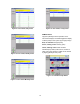
Figure 9: Flow Totals, Daily Flows Figure 12: Flow Totals, Yearly Flows PUMP STATUS Tap [Pump Status] from the Operation menu. This screen displays an animated graphical display of all the pumps in the system (up to eight pumps). Red, no animation: Stopped pump Green, rotating center: Running pump Yellow, flashing center: Fault condition Individual pump stats (runtime hours, number of starts, and pump capacity in GPM) can be viewed by tapping [Stats] for each pump.
Figure 14: Individual Pump Stats Figure 15: Booster Monitoring Screen Automated Lake (ALS) Monitoring Screen This screen is used to monitor the Automated Lake Screen. ‘Accum Hours’ is the total accumulated time ALS has been running for. ‘ALS Switch’ denotes the position of ALS switch on the enclosure. ‘Cleaning’ and ‘Flushing’ denote if the respective cycles are on or off. AUXILIARY EQUIPMENT STATUS Tap [Aux. Equipment Status] from the Operation menu.
Lake Level/Transfer/Timed Pump Monitoring Screen: Figure 18: Simple Filters Monitoring Screen Scanner Filters Monitoring Screen The scanner filter monitoring screen shows the status of a single filter with up to eight chambers. Figure 17: Lake Level Controls Monitoring Screen This screen allows you to see the status of the Lake Level/Timed pump control system at a glance.
NOTE: Be sure to scroll to the bottom of the alarm events list before using [Ack All] to ensure that all alarms have been viewed. LOCKOUT VIEW Tap [Lockout View] from the Operations menu. Lockouts are common when water usage and power restrictions limit pump usage to a certain time. Alarm notifications are color coded. Red: Active, Unacknowledged Alarm Green: Active, Acknowledged Alarm Different lockouts may be viewed using the numbered tabs at top.
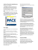
Figure 24: KWH Records, Daily Usage Figure 27: KWH Records, Yearly Usage NOTE: KHW Metering and records are subject to calibration and will only monitor the loads connected to the measurement equipment, primarily irrigation pumps. The records are intended as a reference to plan irrigation for maximum efficiency and are not to be used as a custody transfer or billing meter. Setup Menu Tap [Setup] from the Home screen. The Setup menu is available for Supervisor use only.
This screen allows the date and time to be set, and synchronized for the PLC and HMI. Tap [Synchronize] to synchronize HMI & PLC date and time. In a new pop up screen, enter the date and time. Tap [Set Date/Time – Close] to save changes. Tap [Clear Totalizers] to clear all totalizers. Note that when the HMI time is set, the HMI will automatically sync the PLC time once/day.
Figure 32: Individual Lockout Setup Figure 34: Security Setup Figure 33: Parameter Tab in Lockout Setup The screen shown in Figure 32 sets up a lockout for Friday beginning at 4:59 AM. The duration is set to be 1 hour and 1 minute. Thus this lockout will end at 6:00 AM on Friday. The animated display gives an indication about time. The Parameter tab enables a user to define Combo number, maximum pressure, and maximum speed in RPM. SECURITY SETUP Tap [Security Setup] from the Setup Menu.
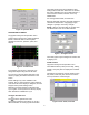
AUXILIARY SETUP Tap [Auxiliary Setup] from the Setup menu. Some These screens allow you to setup and configure any auxiliary equipment. Check any auxiliary equipment that needs to be set up. Each enabled item requires an IP address to communicate to the PLC using the Modbus protocol, which can be entered by double clicking on the IP address field. Default IP addresses can be found in Appendix E. Note: Pace 5.0+ supports integrated auximilary equipment.
pump will be allowed to run during the “enabled” period when the level in the controlled lake calls for the pump to run. If no level control is also configured, the pump will run after the start time and for the duration specified. Setting up the timed operation will be described in detail below. Start and Stop delays apply to level control and are used to de-bounce, or account for wave action on the probes or transducer signal.
∆P Present (sec) is the time between flushes when differential pressure is on, or when the analog differential pressure is less than the differential setpoint. Check the ‘Wye’ checkbox to enable a Wye filter, (which doesn’t use ∆P) and enter values in editable fields. Tap [Next] to move to the next Auxiliary Setup screen. Figure 39: Lake Level Controls Setup Timed Pump Setup (Non-Integrated only) This screen allows you to enable the timed pump setup.
Figure 43: VFD Bypass Figure 46: Fertigation SP Alternate SP Tap [Alternate SP] from the Options Setup Menu. Database Settings This feature helps make changes to database settings. The database is used to send and receive information from the irrigation control system. The “Gateway” software should be installed on the irrigation computer and network connections confirmed before enabling the remote database connection.
addresses will generate an SMS text message to the cellular phone. T-Mobile: phonenumber@tmomail.net Virgin Mobile: phonenumber@vmobl.com Cingular: phonenumber@cingularme.com Sprint: phonenumber@messaging.sprintpcs.com Verizon: phonenumber@vtext.com Nextel: phonenumber@messaging.nextel.com US Cellular: phonenumber@email.uscc.net Figure 47: Database Settings SunCom: phonenumber@tms.suncom.com Powertel: phonenumber@ptel.
the internet) or by navigating the router’s administration pages. In the pop up screen, enter your username and password to log in. After the HMI interface opens, the user type (from Guest to Supervisor) may be changed by the standard procedure described for touch panel log in. Web Reports Figure 48: Email Settings Internet users of the HMI interface can also view and print different reports. There is an Alarms Report, Historical Report, Usage Report, and Factory Reports.
Pump Run Log: Graphically displays the pump operation for the time frame selected. These are color coded: • Green - indicates pump is running • Blue - indicates pump is running on VFD. • Red - indicates pump is in a fault condition. Variables Graph: Line graph displays colorcoded information for key variables over a specified time. The top bar of the graph also has zoom, period, and legend options. The grid below displays variable data. Click […] to choose line colors.
Figure 51: Alarms & Events Figure 53: Usage Report All reports can be printed using [Print], after a printer has been set up by clicking on [Print Setup]. Smart Phone and PDA access: A simpler web page is available for smart phone access. The IP address of this page is the external address determined in appendix “G”, but a specific page address is required to access the simplified page: “/sma/logon.asp” where is the external IP address. Note that “192.168.1.
Appendix A–Glossary of Terms The terms used in this manual are defined in the Glossary of Terms. In addition, other industry specific or product-specific terms are included that may be used by technicians or customer service when talking about your pumping system. Across-the-line (XL) Applying 100% of line voltage to a motor during startup and run. A simple large relay with a contact for each power phase (for 3 phase) is used to control the motor OFF/ON.
Filter A device used downstream of the pumps to clean the water being pumped into the irrigation. These devices are typically self-cleaning, but require hardware/software to self-clean. Fixed speed Pumps run at a fixed RPM, defined by the motor windings and the frequency of the line voltage (50/60 Hz). Frequency (Hz) The number of oscillations per second of any system. Typically used to refer to electrical systems, such as AC power line frequency, or variable speed drive output frequency.
Phase monitor A device that analyzes incoming voltage and determines whether all voltage parameters are acceptable and the phase sequence is correct. PLC Programmable Logic Controller. A very robust/rugged computer designed for equipment control in harsh environments. PM pump Pressure Maintenance Pump. Handles very light flow rates and leaks to prevent the main pumps from cycling. Pressure reducing valve (PRV) A control valve designed strictly for maintaining a specific downstream pressure.
Xylem 1) The tissue in plants that brings water upward from the roots; 2) a leading global water technology company. We’re 12,700 people unified in a common purpose: creating innovative solutions to meet our world’s water needs. Developing new technologies that will improve the way water is used, conserved, and re-used in the future is central to our work. We move, treat, analyze, and return water to the environment, and we help people use water efficiently, in their homes, buildings, factories and farms.