INSTRUCTION MANUAL 19-001-350R2 THIS MANUAL IS FOR TECHNICIAN USE ONLY PACE™ Integrated Pump Controller Human Machine Interface (HMI) for the Silent Storm VFD Pumping System TECHNICIAN GUIDE
Acknowledgements All materials ©2013 by Flowtronex, A Xylem company. Flowtronex© is a registered trademark of Flowtronex a Xylem Company. All rights reserved. No parts of this work may be reproduced in any form or by any means - graphic, electronic, or mechanical, including photocopying, recording, taping, or information storage and retrieval systems - without the written permission of the publisher.
TABLE OF CONTENTS Booster Setup ..................................................... 24 ALS Setup ........................................................... 24 Lake Level Controls Setup .................................. 24 Lake Level Controls Setup (Non-Integrated only)26 Timed Pump Setup (Non-Integrated only) .......... 26 Simple Filters Setup ............................................ 26 Simple Filters Setup ............................................ 26 Scanners Filter Setup .......................
For additional questions, contact: XYLEM FLOWTRONEX After Hours technician for emergency assistance: (214) 454-5768 support@flowtronex.com 8:00 AM to 5:00 PM Central time (800) 786-7480 x3 5:00 PM to 8:00 AM Central time TABLE OF FIGURES Figure 1: Basic Operation .......................................7 Figure 2: Connection for USB Keyboard (c). ..........7 Figure 3: Enhanced Key Pad ..................................8 Figure 4: Basic Screen Layout ................................
WARRANTY INFORMATION Company warrants title to the product(s) and, except as noted below with respect to items not of Company’s Manufacturer, also warrants the product(s) on date on shipment to Purchaser, to be of the kind and quality described herein, and free of defects in workmanship and material.
Introduction CAUTION: Equipment Damage Hazard To Clean the equipment: This manual is written for Flownet Technicians and is an introduction to the Flowtronex PACE HMI (Human Machine Interface). The HMI is a browserbased system which allows the user to interact with the settings and reports of the pumping system. This manual only covers the HMI aspect of the system. Please see the Silent Storm VFD Pumping System Instruction Manual for any questions not related to the HMI.
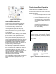
Touch-Screen Panel Operation This Flowtronex® Pace HMI device manual describes the operation of the touch-panel display, located on the enclosure door of the control unit of the pumping station. • Use a stylus to tap the buttons or fields when using the touch-screen panel. • Use the Enhanced Key Pad to enter text or numbers in blank fields. Tap and hold the stylus in a blank field to open the Enhanced Key Pad pop up screen. • A USB Keyboard may also be used instead of the Enhanced Key Pad.
ENHANCED KEY PAD Tap and hold the stylus in an editable field (indicated by a white background) to open the Enhanced Key Pad. To use an Enhanced Keypad: • To clear an entry, tap backspace over entry. • To close key pad without saving on the key entries, tap the red pad.
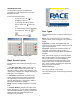
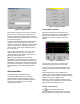
Figure 6: Operation Menu Figure 5: Log in Screen SYSTEM VIEW & TRENDS Default user is a Guest user. No log in is required. Tap [System View] from the Operation menu. To log in as a Technician, tap [Technician], and then tap on the empty Password field to enter the Technician password. Tap [OK] to log in or [Cancel] to exit without logging in. System View accesses color-coded operational trends or historical data for several system variables such as flow, pressure, speed, and setpoint.
The trends will be shown for the Duration value, ending at the current time. When ‘Now’ is checked, the system defaults to the current date and time. If ‘Now’ has been checked, ‘Duration’ is the only editable field. which is an absolute number because KW is read directly, rather than scaled. Click “Channels” to access the calibration screen directly from the “Configure Data” screen. This screen is accessible also from “Setup”>”Options Setup” and is discussed in detail in that section.
Figure 12: Combo Information This shows the Overpressure accumulator settings. “Not Combo” indicates that OPA will operate at any combo level above 2. “Factor” FLOW TOTALS Tap [Flow Totals] from the Operation menu. Figure 15: Flow Totals, Weekly Flows The totalized values (in GAL) for the daily, weekly, monthly, and yearly flow are displayed in a tabular format. Tap [Next] to successively view the totals for each day, week, month and year. Use the scroll bar to move up and down or left and right.
exception of ‘Booster SP’. This pressure (PSI) value remains same for all installed boosters, and is generally higher than user defined SP. Red, no animation: Stopped pump Green, rotating center: Running pump Yellow, flashing center: Fault condition Red, no animation: Stopped Individual pump stats (runtime hours, number of starts, and pump capacity in GPM) can be viewed by tapping [Stats] for each pump.
The Lake Level Control screen shows the pump number, whether the pump is currently on or off, if the enclosure switch is set to on or off, and also gives a pump’s runtime total in hours. If a well pump is used, the well level is shown in feet in a read-only field. Tap [Next] to move to the next status screen.
The alarms screen shows all current and unacknowledged alarm events. Use the vertical scroll bar to view all alarm events if necessary. Red, no animation: Stopped Green, rotating center: Running Yellow, flashing center: Fault condition The latest alarm flashes in the banner at the top of the screen till it is acknowledged using [Ack All]. Tap [Next] to move to the next status screen.
Figure 28: Events Screen Figure 30: KWH Records, Overview LOCKOUT VIEW Tap [Lockout View] from the Operations menu. Lockouts are common when water usage and power restrictions limit pump usage to a certain time. Different lockouts may be viewed using the numbered tabs at top. The Day selected, the Start Time, the Duration, the Combo number selected, the Combo SP (combo setpoint), and the pump Speed are shown.
Figure 33: KWH Records, Monthly Usage Figure 35: Setup Menu USER SETUP Tap [User Setup] from the setup menu. This menu allows a supervisor to set the date/time, language, colors, and units. A lamp test to check all lamps on the control panel may also be performed. Figure 34: KWH Records, Yearly Usage Note: KHW Metering and records are subject to calibration and will only monitor the loads connected to the measurement equipment, primarily irrigation pumps.
CAUTION: Synchronization should not be done while using the Internet-based remote client as this has the potential to negatively affect the time settings of the system. Syncing should only be performed locally. Figure 38: Individual Lockout Setup Figure 37: Set/Sync HMI-PLC Date/Time Lamp Test Tap [Lamp Test] from the User Setup menu. Holding this button for 3 seconds causes all lights on the control panel to light up briefly. Any bulb that does not light up should be replaced.
Tap [Next] to move to the next System Setup screen. Figure 40: Security Setup SYSTEM SETUP Figure 42: Basic Pump Information Tap [System Setup] from the Setup Menu. Zone Configuration The number of flow zones is adjusted here. Up to 7 zones can be selected. This controls how many flow totalizers are operable. Each flow zone will keep track of water usage by day, week, month and year (5 years).
up fluctuations that cause the meter to generate undesirable small flows when the pumps are not running. Alarm Setup This screen allows you to select various alarm types from the drop down menu, and fill in the required settings for each alarm. Pump Configuration Each pump can be selected from a drop down menu in this screen. Each pump can be assigned a group, type, and number of VFDs that are going to be used.
Pumps using this PID Set: This is the final System Setup Screen. Tap [Previous] to move to the prior System Setup screen or tap [Setup] to return to the menu. The decision on which PID set to use is based on the “best” fit of pumps running on VFD and the pumps selected here. Read: FIELD SETUP Click “Read” to read the PID values from the PID group set selected (this is automatically clicked for you when you enter the screen). Tap [Field Setup] from the Setup menu.
response to rapid changes in pressure, regardless of the value of the pressure. This system uses this to begin reducing VFD output speed when pressure is rising quickly, helping to avoid overshoot. The system can also detect fast pressure drops to begin increasing VFD output speed before large errors are detected, increasing the systems responsiveness. cause the system to “get behind” in response to a large change in demand.
helps the system to reach the setpoint faster, but at the same time the system may overshoot the setpoint very quickly since the PID does not have enough time to react to the fast occurring changes. A very low value will make the system take a lot of time to reach the setpoint. Start/Stop Inhibit : The rate at which the system will inhibit pump starts or stops as the pressure rise or drops during the decision process. Generally 0.5-1.0 is adequate to reduce pump cycling.
VFD to go into “Bypass Mode” which means they will operate as fixed-speed pumps. Start: Start a specified combo when the difference between the actual pressure and user defined SP exceeds this value. Stop: Stop a specified combo when the difference between the actual pressure and user defined SP exceeds this value. Tap [Next] to move to the next Field Setup screen. Figure 50: Combos Combo Pumps This screen allows you to configure which pump will be used in which combo.
You can navigate the status screens for each device that has been set up by tapping [Previous] or [Next]. NOTE: The screens described below will only be displayed if they are applicable to the current system. Figure 53: Booster Setup ALS Setup In this screen, Flush Times and Flow Rates may be edited. Time until Flush (sec): Time period between flushes. Figure 52: Auxiliary Equipment Setup Duration of Flush (sec): Time duration for the flush.
evaluated to determine which will run, based on run hours and switch settings. Timed pump can be configured with or without level control. A timed pump will be enabled to run on the days specified, after the start time and for the duration specified. If also level controlled, then the pump will be allowed to run during the “enabled” period when the level in the controlled lake calls for the pump to run.
on a day that is not selected if the previous days duration setting extends past midnight. Figure 58: Lake Level Controls Setup Figure 57: Integrated Timed Pump configuration Timed Pump Setup (Non-Integrated only) This screen allows you to enable the timed pump setup. If the ‘Feedback Enable’ box is checked, the pump will send feedback to the PLC. For example, assume the pump is configured as shown above.
∆P Present (sec) is the time between flushes when differential pressure is on, or when the analog differential pressure is less than the differential setpoint. Check the ‘Wye’ checkbox to enable a Wye filter, (which doesn’t use ∆P) and enter values in editable fields. Tap over any field to access the desired setup options. Tap [Next] to move to the next Auxiliary Setup screen. Figure 62: Options Setup Menu VFD Bypass Tap [VFD Bypass] from the Options Setup Menu.
I/O names available and those can be edited to match the new variable for scaling. CAUTION: Before using this feature or changing any settings on this screen, please call customer service. Tap [Close] to return to the Options Setup Menu. Tap [Close] to return to the Options Setup Menu. Figure 64: Analog Scaling ActiveX and IP Updates Tap [ActiveX and IP Updates] from the Options Setup Menu. Figure 66: WinCE Remote Access By default both ISSymbol URL and Agent URL are automatically populated.
irrigation PC. While the system will operate correctly, unnecessary events and exceptions are generated which can load the HMI processor and take up valuable event-table space. Figure 68: Pressure SP Figure 70: Database Settings After enabling the database connection, the HMI must be restarted with the Gateway software running on the host irrigation computer. This can be accomplished through cycling power or by shutting down and restarting the application.
If the colored box remains green after hitting Send, the configurations are working correctly. If the box turns red there has been an error. The number after “Status” indicates the type of error, table for which can be found in Appendix F. Additional troubleshooting options for email configuration can also be found in Appendix F. entered by separating the email addresses with a semicolon. Examples: Me@gmail.com; TheBoss@test.com; SecondGuy@test.com; 555555555@verizon.net.
• Click on the buttons with your mouse. • Use your mouse to click in a blank field. Enter text or numbers using a standard PC keyboard. Remote Software Log In An identical version of the HMI software may be accessed remotely by an Internet IP (Internet Protocol) address. Type the following address into an internet browser: From within your network (at the maintenance facility), open your web browser and type the following URL into the address line: http://192.168.1.15.
Web Reports Menu After logging in, web reports menu is displayed containing the following buttons, Login, Trend View, Alarms Report, Historical Report, Usage Report, Factory Report, Print Setup, Print, and Exit. Pump Run Log: Graphically displays the pump operation for the time frame selected. These are color coded: NOTE: Factory Report is available only to a supervisor or technician. It includes a list of values of various PLC registers and is not covered further in this guide.
Figure 76: Alarms & Events Figure 78: Usage Report All reports can be printed using [Print], after a printer has been set up by clicking on [Print Setup]. Smart Phone and PDA access: A simpler web page is available for smart phone access. The IP address of this page is the external address determined in appendix “G”, but a specific page address is required to access the simplified page: “/sma/logon.asp” where is the external IP address. Note that “192.168.1.
Appendix A–Glossary of Terms The terms used in this manual are defined in the Glossary of Terms. In addition, other industry specific or product-specific terms are included that may be used by technicians or customer service when talking about your pumping system. Across-the-line (XL) Applying 100% of line voltage to a motor during startup and run. A simple large relay with a contact for each power phase (for 3 phase) is used to control the motor OFF/ON.
Filter A device used downstream of the pumps to clean the water being pumped into the irrigation. These devices are typically self-cleaning, but require hardware/software to self-clean. Fixed speed Pumps run at a fixed RPM, defined by the motor windings and the frequency of the line voltage (50/60 Hz). Frequency (Hz) The number of oscillations per second of any system. Typically used to refer to electrical systems, such as AC power line frequency, or variable speed drive output frequency.
Phase monitor A device that analyzes incoming voltage and determines whether all voltage parameters are acceptable and the phase sequence is correct. PLC Programmable Logic Controller. A very robust/rugged computer designed for equipment control in harsh environments. PM pump Pressure Maintenance Pump. Handles very light flow rates and leaks to prevent the main pumps from cycling. Pressure reducing valve (PRV) A control valve designed strictly for maintaining a specific downstream pressure.
Appendix B ─ Panel Switch Settings The following table shows the results of different switch settings on the main enclosure panel: Table 1 – Enclosure Panel Switches 37
Appendix C ─ Networking Options 38
Appendix D–Typical Alarms Configuration Table 2 – Default Alarms / Faults 39
Appendix E – Default IP Addresses for Auxiliary Devices Integrated devices are all addresses at the Main PLPC’s IP address, normally 192.168.1.10.
Appendix F – Email Troubleshooting DETERMINING THE IP ADDRESS OF THE SMTP SERVER On your Windows PC, Click “Start”, “Run”, type in “CMD” in the dialog and press enter. You will see a DOS prompt window similar to that below. Type “ping” followed by the server name of your SMTP service. Your email provider will be able to supply these server names as a standard part of the information needed to set up your email for outlook or other email programs.
Look at the line following your command entry, this will contain the IP address of the SMTP server. In this case, smtp.runbox.com is at IP address 87.238.52.70. Double-check the POP3 server for the same IP address. Same procedure, but use your pop3 server name in the ping statement.
TROUBLESHOOTING GENERAL EMAIL FAILURES The following are some common problems encountered when configuring email settings. Double check each setting to ensure the correct information was entered. 1. Attempting to use the server name rather than the IP address in the SMTP field. 2. Using an incorrect IP address - determine the IP address from the procedure above. 3. Entering an invalid user. Make sure the user field matches the account. Also make sure the “From” field matches the user information exactly. 4.
Troubleshooting Email Send Failures The following table gives the number codes associated with failures received after tapping [SEND] to do a test-run of the email addresses and the SMTP: Value Description 0 Success 1 Invalid format for parameter 1 (Subject) 2 Invalid format for parameter 2 (Message) 3 Invalid format for parameter 3 (To) 4 Wrong number of parameters 5 Start Socket error 6 Error getting host IP Address (i.e.
• If successful, be sure and type “quit” . It’s bad form to leave the server hanging though it will reset the session itself. • If you are unable to connect, attempt to Telnet to the POP3 server on port 110. Successful Telnet to the POP3 server but unsuccessful telnet to the smtp server is typical of a port 25 block by the ISP. They often block port 25 to prevent spammers from using home and unwary business accounts for spam generation. A call to your ISP will usually resolve the problem quickly.
Appendix G: Computer Setup and Determining the IP address of your pump station In order to access your pump station and to integrate your pump and irrigation systems, you will need to install the software that came with your pump station. Note: Pace will integrate only with Toro Lynx irrigation systems at this time, though some level of interface is planned for other irrigation system controls at a future time. This is the CD called the Flowtronex Gateway. Place this CD in your CD ROM drive.
Another window will come up. Select Properties: Highlight Internet Protocol (TCP/IP). If there are two entries, one for v6 and one for v4, select v4 as shown. Then select Properties.
Select “Use the following IP address” Check with your IT department or internet service provider for proper DNS server settings. These should be no different than your settings before installing the router. DETERMINING THE IP ADDRESS: Determining the IP address to use to communicate with your pump station remotely can be as easy as asking your IT professional, or somewhat more complicated, requiring you to access your routers status page.
Select the “Status” page from the menu at the top of the screen. Scroll down the page to the “WAN” status to see the IP address assigned by your Internet service provider. Please note, if your network is more complicated than a simple connection through a cable or DSL modem, please consult your IT department. The procedure outlined above can only supply the IP address of the router, and therefore the IP address of your PC, with reference to the network the router is connected to.
Appendix H – General Networking and Router Configuration Discussion: Regarding the requirement for a fixed IP address: This is not a requirement of the Flowtronex Pace control system. This is required so the user attempting to access the system remotely can find the machine on the internet. Without a fixed IP address, the computer is at one of 4,228,250,625 theoretically possible addresses, though usually addresses are assigned within a specific range of a few thousand.
The user would access his station by requesting a web page at http://76.199.50.60 (default port is 80 for HTTP). Note how the pump station router, the last in the line, redirects the port requests to specific device (IP address) at the same port (80). All other routers are just passing along the message, keeping the port #s essentially intact.
Generally, the WAN port of the pump station router is connected directly to the cable or DSL modem, so the complex routing configuration is not required. The pump station router is usually configured as follows: WAN LAN Port Forwarding Pump Station Router 76.199.50.60 (Supplied by internet service provider) 192.168.1.1 80->192.168.1.15:80 81->192.168.1.16:80 82->192.168.1.
Xylem 1) The tissue in plants that brings water upward from the roots; 2) a leading global water technology company. We’re 12,700 people unified in a common purpose: creating innovative solutions to meet our world’s water needs. Developing new technologies that will improve the way water is used, conserved, and re-used in the future is central to our work. We move, treat, analyze, and return water to the environment, and we help people use water efficiently, in their homes, buildings, factories and farms.