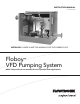
INSTRUCTION MANUAL 19-001-251R3 INSTALLER: PLEASE LEAVE THIS MANUAL FOR THE OWNER’S USE. Floboy™ VFD Pumping System NOTE: This product is not intended for use in potable water applications.
Acknowledgements ® All materials ©2013 by Flowtronex , an Xylem company. ® Flowtronex is a registered trademark of Xylem Flowtronex. All rights reserved. No parts of this work may be reproduced in any form or by any means - graphic, electronic, or mechanical, including photocopying, recording, taping, or information storage and retrieval systems - without the written permission of the publisher.
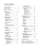
TABLE OF CONTENTS ACKNOWLEDGEMENTS TABLE OF CONTENTS ·········································· I TABLE OF FIGURES ············································· II WARRANTY INFORMATION ··································· 2 SAFETY······························································· 3 Safety instructions .................................................... 3 Safety Reminders ..................................................... 3 Additional Safety Information ...................................
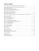
TABLE OF FIGURES Figure 1: Typical Floboy suction and discharge piping, Boost applications ....................................................... 5 Figure 2: Typical Floboy suction and discharge piping, Lift applications ........................................................... 5 Figure 3: Sample Nameplate ............................................................................................................................. 6 Figure 4: Typical Floboy installation on slab. ..........................
NOTE: The information contained in this book is intended to assist operating personnel by providing information about the characteristics of the purchased equipment. It does not relieve the user of their responsibility of using accepted engineering practices in the installation, operation, and maintenance of this equipment.
WARRANTY INFORMATION Company warrants title to the product(s) and, except as noted below with respect to items not of Company’s Manufacturer, also warrants the product(s) on date on shipment to Purchaser, to be of the kind and quality described herein, and free of defects in workmanship and material. foregoing remedies. The same obligations and conditions shall extend to replacement parts furnished by Company hereunder. Company shall have the right of disposal of parts replaced by it.
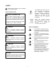
SAFETY Read all safety information prior to installation of your pumping system. All operating instructions must be read, understood, and followed by the operating personnel. Flowtronex accepts no liability for damages or operating disorder which are the result of non compliance with the operating instructions. SAFETY INSTRUCTIONS SAFETY INSTRUCTION This is a SAFETY ALERT SYMBOL. It is used to alert you to potential personal injury hazards.
ADDITIONAL SAFETY INFORMATION MAINTENANCE SAFETY: This pump has been designed for safe and reliable operation. A pump is a pressure-containing device with rotating parts that could be hazardous. Operators and maintenance personnel must realize this and follow necessary safety measures. Proper safety procedures must be followed. Xylem Flowtronex shall not be liable for damage or delays caused by a failure to observe the instructions in this manual. • Always lock out power.
GENERAL DESCRIPTION PRODUCT DESCRIPTION Floboy Pumping Systems are self-contained, pre-assembled and factory-tested pumping systems. Floboy utilizes state of the art technology, yet employs a simplistic and straight forward design that makes installation, operation and maintenance an easy task, even for the most inexperienced of operators.
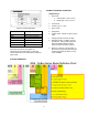
EXAMPLE: FBSNV4BF10D46R3ABD 08FB=Floboy II 1. Size Code a. S=Small (52”l x 40”w x 45”h) b. M=Mid (64”l x 53” w x 55” h’) 2. Lift or Boost 3. Control Type: V = VFD Figure 3: Sample Nameplate Field 4. Pump model 5. Horsepower Explanation Voltage Required input voltage SCCR Short circuit current rating Phase Number of motor phases FLA Full load amps Hz Required frequency (hertz) Max. HP Maximum horsepower 6. Impeller Code. Specific to type of pump used. 7. Voltage (46=460, 23=230, 20=208) 8.
HANDLING FIELD CONNECTION DIAGRAMS Qualified personnel should unload and handle the unit. Prevent damage due to dropping or jolting when moving the unit. Thoroughly inspect the unit for damage upon receipt. Immediately notify the carrier of transportation damage. Ensure that sensing lines are free of crimps and kinks. Actual equipment manufacturers/models installed are system specific. Refer to specific manufacturers’ Installation, Operation & Maintenance Manuals for details unique to each component.
RECEIVING the freight company a clear receipt for goods that have been damaged or lost in transit you do so at your own risk and expense. PREPARING TO RECEIVE THE PUMP STATION If you receive the pump station and subsequently discover damaged equipment or lost goods that were concealed by the packaging you must contact the freight company immediately. Do not proceed with the system's installation until the freight company has inspected this equipment.
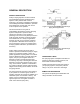
Concrete slabs should be at least 6" thick and be constructed in a monolithic pour from 3000 psi concrete and #5 rebar. The slab should be sized with a minimum of 6" clearance between the edge of the slab and the edge of the pump station. Please note that it is the customer's responsibility to meet all local code and seismic requirements. WARNING: Falling Objects Hazard Heavy Load, May Drop If Not Lifted Properly. Figure 4: Typical Floboy installation on slab.
and the pump inlet (Example: 4" pipe requires 4" x 6 = 24" long piece of straight pipe between the elbow and the pump inlet). A. Piping should be sized in accordance with the architect, engineer or factory's direction. B. Piping should be constructed of spring reinforced suction hose, steel or high density poly pipe. All joints should be fusion welded or flanged and pressure tested to ensure a leak proof connection.
Figure 6: Proper suction lift principles Figure 7: Improper suction lift application 11
DISCHARGE PIPING ELECTRICAL CONNECTIONS Like the suction assembly, the discharge piping requires adherence to certain rules and conditions in order to minimize future problems. The following list should be observed when designing and installing the discharge assembly: The pumping system is pre-wired at the factory and includes all internal wiring necessary to function. For relay start systems, the customer must still wire any external controllers and devices to the relays inside the control panel.
START-UP AND ADJUSTMENTS Assume the actual voltage readings on a nominal 480 volt system are: Floboy Pumping Systems are pre-tested in the factory and all controls are adjusted for the operating conditions specified. However, there are certain checks that must be performed prior to energizing the pump station in order to prevent the possibility of component damage. These voltage checks can be performed by a qualified, licensed electrician.
water when the motor is energized. For pump stations whose inlet is supplied with water under pressure or from an elevated reservoir, the priming process is not required other than the removal of trapped air in the suction pipe. A petcock on the top of the pump volute should be opened to allow air to escape and the volute to fill with water. Once the air has completely escaped, close the petcock. from "Off" to "On".
pump. Cavitation is a condition that may permanently damage the pump if allowed to continue. It is usually caused by improper suction installation or by over demanding the pump. It is not uncommon to experience cavitation when filling the discharge piping since empty piping encourages pump over demand if the station isolation valve is opened too far or too quickly. Should you notice this sound, gradually close the isolation valve until the noise intensity subsides.
STATION OPERATION This section covers the sequence of operation for your station including: Door Switch Operation, Automatic Operation, and System Safeties. LDP Override DOOR SWITCH OPERATION Individual Pump Switches Allows operator to select which pumps operate: NOTE: Pumps have an OFF/ON switch. OFF Selected pump does not operate, regardless of any other switch position. This position prevents a low-discharge pressure fault from shutting down the pump station.
AUTOMATIC OPERATION NOTE: As downstream pressure drops to more than 5 PSI below set point, the PM pump starts up. It runs until the system pressure builds up to 5 PSI above set point, and then shuts off. Overview The primary benefit of Variable Speed Pumping (VSP) Systems is to ensure surge-free starts and stops while maintaining a constant down-stream line pressure with no mechanical pressureregulating valve.
pressure at the set point. This is the operation sequence for Combo 2. NOTE: Manual operation is rarely used. However, it does allow for operation of individual pumps for testing purposes. When the flow decreases, the VFD slows down to maintain a constant discharge pressure. Eventually as the speed decreases, a set point is reached where the VSP is not pumping any water. Because the VFD speed keeps dropping as the flow decreases, the discharge pressure would never get above the set point.
CONTROLLER BYPASS OPERATION Alarm or Fault Low Discharge Pressure Overview This is an abnormal operating mode and would be used if the controller was not operable and there is need to irrigate. High Discharge Pressure Low Inlet Pressure (Optional) Loss of Prime (Optional) WARNING: Controller Bypass Hazard Low Level (Optional) Individual Pump Faults This mode of operation should be used as a last resort. Constant operator monitoring is REQUIRED when this mode is used.
reference to set point). There is a time delay of 60 seconds, before the station faults that is designed to give the system time to adjust the pressure to below this point. These values might vary on your station. CAUTION: Delta Pressure Setting Hazard Do not adjust the bottom dial. This is a delta pressure setting, and is not used. This dial must be adjusted fully counter-clockwise (0 position).
INDIVIDUAL PUMP FAULTS Adjustment of the overload set point is performed using the blue dial on the left front face of the device. Pump faults are usually caused by the thermal overload tripping, or circuit fault that causes the pump NOT to start when requested. Once the overload has been reset, individual pump faults require turning the individual pump switch to the OFF position, and then back ON (rearming). Overload Protection Overload Protection is standard on all pump stations.
Figure 12: Pump Status Indicators PRESSURE SET POINT ADJUSTMENT Figure 10: Floboy controller. CAUTION: Equipment Damage Hazard Be careful not to set the value too low for the pump you are using, nuisance overloads can occur. Also, do not set the value too high for your systems piping or damage may occur. The “Menu” key provides access to the slide-out menu which can be touched directly for navigation and also serves as a reminder of the function keys definition in the context of the current screen.
Figure 17: Performance Graph Press the Alarm button to view up to 32 previous alarms. Figure 15: Entering the password for the set point screen This allows the user to edit the set point. Touch the button next to the Set point value: Figure 18: Alarms Screen Figure 16: Changing the set point Alarms are shown as shown in figure 15 below. Change the set point as required. Be careful not to set the value too low for the pump you are using, nuisance overloads can occur.
START SETTINGS. Select combo and parameters Pressing the Menu button from the main screen provides access to the menu system. to set via buttons at top of screen. Pressure is in reference to set point. Flow rate is used for Flow Start systems. Figure 20: Menu Access to the main functions of the controller is available from the menus. Figure 23: Stop Settings STOP SETTINGS: Pressure is in reference to set point, flow rate is used when flow stop is required/configured.
Figure 25: Speed Test Figure 27: Safety, Others SPEED TEST: Delay is how long the controller Inlet water faults are controlled under “Others”. Short times should be used as these faults can cause serious damage if the timers are set too long. 5 seconds is all that is required. High Pump Temp is also controlled here. The delay is how long between a high pump temp signal and the pump is shut down. 5 seconds is all that is required.
MAINTENANCE Motor lubrication: If you have a grease filled bearing, ensure that grease is not all over the inside of the motor and down in the bottom of the motor. This could be a sign of over-filling. Refer to the motor manufacturer's lubrication instructions. Maintenance is an investment that will pay dividends in the form of improved reliability and durability. Site maintenance checks are a matter of day to day, week to week care that is important to the proper operation of the pumping equipment.
WINTERIZING THE PUMP STATION 7. Connect hose to hose bib on the pump station. The bib is usually found under the discharge manifold for the pumps, or at the end of the hydro-pneumatic tank. Slowly, open the hose bib ball valve on the pump station. Slowly, open all ball valves on the pump station. Wait until pump station pressure reads 0 PSI before closing the hose bib ball valve. CAUTION: Equipment Damage Hazard Your pumping system must be properly winterized before storage.
TROUBLESHOOTING 1. If a troubleshooting step needs to be performed by a qualified person, it is labeled “To be performed by a qualified person only.” 2. Steps that can be performed by unqualified persons are not labeled. 3. Qualified persons are those who have been trained in avoiding the electrical hazards of working on or near exposed energized parts. Only qualified persons may open the electrical enclosure. 4. Unqualified persons are those with little or no such training.
Bad relief valve or pilot valve seat. Rebuild or replace valve. Low suction pressure or supply water restriction. Call the city if the city water pressure is lower than the normal or published value. Check the supply piping for obstruction. HIGH DISCHARGE PRESSURE FAULT Cause Cure High system pressure setting too low. Access “Menu->Safety->Low pressure: Set Point. Verify is approx. 15 psi higher than set point. This is a gage pressure setting, not relative to set point.
Inlet pressure switch is set too high. To be performed by a qualified person only. Check the pressure switch setting. (Located on lower left side of outside of enclosure.) Pressure sensing line to pressure switch is clogged or valved off. Ensure the valve is open, and blow out line if necessary. Pressure is actually low – static. If the city supplied water, check with them. If the water is supplied by a tank, check the tank level, and verify that the supply valve is open.
Fault code 2 – DC overvolt (intermediate circuit DC voltage is excessive). To be performed by a qualified person only. Check the input voltage (AC) to the drive. If high, contact the power company. Fault code 6 – DC undervolt (intermediate circuit DC voltage is insufficient). To be performed by a qualified person only. Check the input voltage (AC) to the drive. If low, contact the power company. Fault code 7 – AI1 loss (analog 1 input value is less than minimum value). This can be a nuisance fault.
GLOSSARY OF TERMS AC Alternating Current. The voltage, and therefore current, constantly oscillates positive and negative. For North America, the line frequency is 60 Hz. Some other areas of the world use 50 Hz. Across-the-line (XL) Applying 100% of line voltage to a motor during startup and run. A simple large relay with a contact for each power phase (for 3 phase) is used to control the motor OFF/ON.
Foot valve A device used primarily on horizontal lift applications to maintain pump prime. Frequency (Hz) The number of oscillations per second of any system. Typically used to refer to electrical systems, such as AC power line frequency, or variable speed drive output frequency. This frequency defines the speed of an AC motor. GPM Gallons per minute. Units of flow for US use. Input A way for a control system to detect real-world occurrences. These can be digital or analog.
Speed test The method used to shut down a VSP during normal automatic operation. Temperature switch This is a normally open or normally closed switch that changes output state when the temperature exceeds the set point of the switch. Units Gives context to numbers in the PLC. Units describe what the number is about, such as PSI, GPM. VFD Variable frequency drive. This allows a pump to run at variable speeds. VSP Variable speed pump. Refers to a pump being controlled by the variable frequency drive.
APPENDIX A — FINAL CHECK LIST £ £ £ £ £ £ Is the base unit properly leveled and secured? Are all lubrication points properly lubricated? Is the shut-off valve on to the pump suction open? Is the shut-off valve on the discharge line open? Is the piping properly supported so as to prevent strains on the unit? Is the distribution system purged of debris and air? Is the system filled? CAUTION: Stuffing Box Damage Do not run pumps dry. Fill and vent the pump volute prior to operation.
Xylem Inc. 10661 Newkirk Street Dallas, TX 75220 Phone: 800-786-7480 www.flowtronex.com support@flowtronex.com Flowtronex is a trademark of Xylem Inc. or one of its subsidiaries. © 2013 Xylem Inc.