
User's Manual


Document MV0319P.N
© Xsens Technologies B.V.
MVN User Manual
111
19.6.2 Bony/anatomical landmarks
The positions of bony/anatomical landmarks with respect to the joint origin of the related segment are
presented in the MVNX file, see the <points>tag in the <segment>section. Segments are assumed to
be rigid bodies.
Positions of anatomical landmarks in the global frame (G) can be found by rotating the vector of the
landmark in the body frame (B) to the global frame and adding the global position of the origin.
*G G GB B GB
landmark origin
+ q q p p x
Or in rotation matrix formulation:
G G GB B
landmark origin
+p p R x
The rotation from body to global (
GB
q) and global position of the origin (
G
pos) are given in the MVNX file,
see next section.
a
b
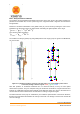
Figure 67: a) Segment coordinate system at each joint origin, as is used in MVN. b) Joint centers
connected, forming a skeleton Legend: x: red, y: green, z: blue
Note that positions of anatomical landmarks are not measured directly as they are with optical
measurement systems. They are computed using the measured accelerations, angular velocities and
rotations in combination with the biomechanical model. Relevant points are used for the detection of
contacts with the external world and as an indication for scaling of segment lengths.
The MVN character mesh (only for visualization) is an abstract representation of the human skeleton;
therefore not all anatomical landmarks are exactly on the mesh. The ribcage is connected to T8 and will
move accordingly.