
User's Manual


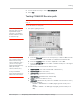
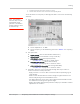
Table Of Contents
- Important Notice
- Safety and Hazards
- Limitation of Liability
- Patents
- Copyright
- Trademarks
- Contact Information
- Revision History
- 1: Introduction
- 2: Technology Overview
- 3: Standards Compliance
- 4: Electrical Specifications
- 5: RF Specifications
- 6: Power
- 7: Software Interface
- 8: Mechanical and Environmental Specifications
- 9: Regulatory and Industry Approvals
- A: Antenna Specification
- B: Design Checklist
- C: Testing
- D: Packaging
- E: References
- F: Acronyms
- Index

Product Technical Specification & Customer Design Guidelines
80 Proprietary and Confidential - Contents subject to change 2400074
Note: The value measured from the DUT is significantly influenced by the test setup and
DUT design (host RF cabling loss, antenna efficiency and pattern, test antenna efficiency
and pattern, and choice of shield box).
GPS standalone connector test
GPS testing should be done on devices that support a dedicated GPS connector.
If the MC7750 supports a dedicated GPS connector/path (that is, not shared with
the diversity connector), then GPS testing may be done by characterizing some
known-good MC devices and checking for carrier to noise levels.
To test the GPS path:
1. Inject a carrier signal at -110dBm, frequency 1575.52 MHz into the GPS Rx
path. (Note that this is 100kHz higher than the actual GPS frequency.)
2. Test the signal carrier-to-noise level at the GPS receiver:
a. AT!ENTERCND (Unlock extended AT command set.)
b. AT!DAFTMACT (Put modem into factory test mode.)
c. AT!DACGPSTESTMODE=1 (Start CGPS diagnostic task.)
d. AT!DACGPSSTANDALONE=1 (Enter standalone RF mode.)
e. AT!DACGPSMASKON (Enable log mask.)
f. AT!DACGPSCTON (Return signal-to-noise and frequency measurements.)
g. Repeat AT!DACGPSCTON five to ten times to ensure the measurements
are repeatable and stable.
3. Leave the RF connection to the Mini Card device intact, and turn off the
signal generator.
4. Take several more !DACGPSCTON readings. This will demonstrate a 'bad'
signal in order to set limits for testing, if needed. This frequency offset should
fall outside of the guidelines in the note below, which indicates that the CtoN
result is invalid.
5. (Optional) Turn the signal generator on again, and reduce the level to -
120dBm. Take more
!DACGPSCTON readings and use these as a reference
for what a marginal
/ poor signal would be.
Note: The response to AT!DACGPSCTON for a good connection should show CtoN within
58 +/- 5dB and Freq (frequency offset) within 100000 Hz +/- 5000 Hz .
Quality assurance testing
Note: QA is an ongoing
process based on random
samples from a finished
batch of devices.
The quality assurance tests that you perform on your finished products should be
designed to verify the performance and quality of your devices.
The following are some testing suggestions that can confirm that the antenna is
interfaced properly, and that the RF module is calibrated and performs to
specifications:
• Module registration on cellular networks