
User's Manual


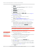
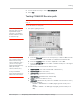
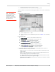
Table Of Contents
- Important Notice
- Safety and Hazards
- Limitation of Liability
- Patents
- Copyright
- Trademarks
- Contact Information
- Revision History
- 1: Introduction
- 2: Technology Overview
- 3: Standards Compliance
- 4: Electrical Specifications
- 5: RF Specifications
- 6: Power
- 7: Software Interface
- 8: Mechanical and Environmental Specifications
- 9: Regulatory and Industry Approvals
- A: Antenna Specification
- B: Design Checklist
- C: Testing
- D: Packaging
- E: References
- F: Acronyms
- Index

Product Technical Specification & Customer Design Guidelines
78 Proprietary and Confidential - Contents subject to change 2400074
Note: The dBm value displayed is calculated to reflect the power at the input connector.
f. AT!RX2=1 (Turn on diversity receiver.)
g. AT!RX2AGC? (Read back the power level, in dBm, from the diversity
receiver.)
Response examples:
· RX2AGC = 0xFFFFFF76 = -84 dBm (Signal generator’s RF port is
OFF)
· RX2AGC = 0xFFFFFFC6 = -69 dBm typical (Signal generator’s RF
port is ON)
h. AT!RX=0 (Turn off main receiver.)
i. AT!RX2=0 (Turn off diversity receiver.)
3. Test limits — Run ten or more good DUTs through this test procedure to
obtain a nominal received power value.
· Apply a tolerance of 5 to 6 dB to each measurement (assuming a good
setup design).
· Make sure the measurement is made at a high enough level that it is not
influenced by DUT-generated and ambient noise.
· The Signal Generator power level should be at least -50 dBm.
· Monitor these limits during mass-production ramp-up to determine if further
adjustments are needed.
Note: The value measured by the DUT depends on the test setup and DUT design. Host
RF cabling loss, antenna efficiency and pattern, test antenna efficiency and pattern, and
choice of shield box all significantly influence the measurement.
Note: When doing the same test over the air in an RF chamber, values are likely to be
significantly lower.
LTE RF receive path test
Note: This procedure segment is performed in Step 13 of the Production test procedure on
page 74.
Tab l e C-1 contains parameters used in the suggested test procedure that follows.
Table C-1: Test settings — Receive path
Mode Test category
Bands
B13 B17 B4
LTE
Frequency
a
(MHz) 753.0 742.0 2134.5
Band 36 37 42
Channel
b
23230 23790 20175