
User's Manual

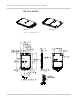
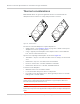

Table Of Contents
- Important Notice
- Safety and Hazards
- Limitation of Liability
- Patents
- Copyright
- Trademarks
- Contact Information
- Revision History
- 1: Introduction
- 2: Technology Overview
- 3: Standards Compliance
- 4: Electrical Specifications
- 5: RF Specifications
- 6: Power
- 7: Software Interface
- 8: Mechanical and Environmental Specifications
- 9: Regulatory and Industry Approvals
- A: Antenna Specification
- B: Design Checklist
- C: Testing
- D: Packaging
- E: References
- F: Acronyms
- Index

Mechanical and Environmental Specifications
Rev 4 Sep.11 Proprietary and Confidential - Contents subject to change 57
Module integration testing
When testing your integration design:
• Test to your worst case operating environment conditions (temperature and
voltage)
• Test using worst case operation (transmitter on 100% duty cycle, maximum
power)
• Monitor temperature at all shield locations. Attach thermocouples to the areas
indicated in
Figure 8-4 on page 56 (Transmitter, Baseband 1, Receiver,
Baseband 2).
Note: Make sure that your system design provides sufficient cooling for the module. RF
shield temperature should be kept below 90
°C when integrated to prevent damage to the
module’s components.
(For acceptance, certification, quality, and production (including RF) test
suggestions, see
Testing on page 71.)