
User's Manual

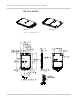

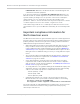
Table Of Contents
- Important Notice
- Safety and Hazards
- Limitation of Liability
- Patents
- Copyright
- Trademarks
- Contact Information
- Revision History
- 1: Introduction
- 2: Technology Overview
- 3: Standards Compliance
- 4: Electrical Specifications
- 5: RF Specifications
- 6: Power
- 7: Software Interface
- 8: Mechanical and Environmental Specifications
- 9: Regulatory and Industry Approvals
- A: Antenna Specification
- B: Design Checklist
- C: Testing
- D: Packaging
- E: References
- F: Acronyms
- Index

Product Technical Specification & Customer Design Guidelines
56 Proprietary and Confidential - Contents subject to change 2400074
Thermal considerations
Embedded modules can generate significant amounts of heat that must be
dissipated in the host device for safety and performance reasons.
Figure 8-4: Shield locations
The amount of thermal dissipation required depends on:
• Supply voltage — See Chapter 6: Power on page 45 for details of max power
dissipation for various operating modes.
• Usage — Typical power dissipation values depend on the location within the
host, amount of data transferred, etc.
Specific areas requiring heat dissipation are shown in Figure 8-4:
• Transmitter — Top face of module near RF connectors. Likely to be the hottest
area.
• Baseband 1 —Top face of module, below the transmitter.
• Receiver — Bottom face of module, behind the transmitter.
• Baseband 2 — Bottom face of module, behind Baseband 1.
To enhance heat dissipation:
• Maximize airflow over / around the module.
• Locate the module away from other hot components.
• If possible, use the mounting holes to attach (ground) the device to the main
PCB ground or a metal chassis.
Note: Adequate dissipation of heat is necessary to ensure that the module functions
properly, and to comply with the thermal requirements in
[11] PCI Express Mini Card
Electromechanical Specification Revision 1.2.
Caution: Thermal putty is not recommended — incorrect application of the material could
require exessive pressure to be applied when seating the board, resulting in damage to the
board.
Transmitter
Baseband 1 Baseband 2
Receiver
Top Bottom
Pin 1
Pin 1