
User's Manual
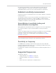
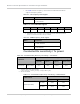
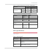
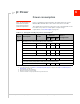
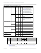
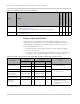
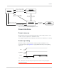

Table Of Contents
- Important Notice
- Safety and Hazards
- Limitation of Liability
- Patents
- Copyright
- Trademarks
- Contact Information
- Revision History
- 1: Introduction
- 2: Technology Overview
- 3: Standards Compliance
- 4: Electrical Specifications
- 5: RF Specifications
- 6: Power
- 7: Software Interface
- 8: Mechanical and Environmental Specifications
- 9: Regulatory and Industry Approvals
- A: Antenna Specification
- B: Design Checklist
- C: Testing
- D: Packaging
- E: References
- F: Acronyms
- Index

Power
Rev 4 Sep.11 Proprietary and Confidential - Contents subject to change 49
Figure 6-1: Voltage / temperature monitoring state machines
Power interface
Power ramp-up
On inital power up, inrush current depends on the power supply rise time — turn
on time >100
µs is required for < 3A inrush current.
The supply voltage must remain within specified tolerances while this is occurring.
Power-up timing
The unit is ready to enumerate with a USB host within a maximum of 3–5
seconds after power-up.
Figure 6-2 on page 49 illustrates the power-up timing
sequence.
Figure 6-2: Power-up timing diagram
Note: Startup time is the time after power-up when the modem is ready to begin the
enumeration sequence.
Off mode
Handled by Power
State state machine.
Normal mode
Low power mode
Handled by Power
State state machine.
current_vcc > VOLT_LO_NORM
current_temp <= TEMP_HI_NORM
current_vcc < VOLT_LO_CRIT
current_temp > TEMP_HI_CRIT
current_vcc > VOLT_LO_NORM
current_temp < TEMP_HI_NORM
current_vcc < VOLT_LO_WARN
current_temp > TEMP_HI_WARN
current_vcc < VOLT_HI_NORM
current_temp > TEMP_NORM_LO
current_vcc > VOLT_HI_CRIT
current_temp < TEMP_LO_CRIT
(Manual transition)
Host asserts
W_Disable#
Normal mode
Low supply voltage warning
or
High temperature warning
Enumeration
3.3V
W_Disable#
USB D+
Startup time