
User's Manual
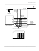

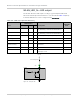

Table Of Contents
- Important Notice
- Safety and Hazards
- Limitation of Liability
- Patents
- Copyright
- Trademarks
- Contact Information
- Revision History
- 1: Introduction
- 2: Technology Overview
- 3: Standards Compliance
- 4: Electrical Specifications
- 5: RF Specifications
- 6: Power
- 7: Software Interface
- 8: Mechanical and Environmental Specifications
- 9: Regulatory and Industry Approvals
- A: Antenna Specification
- B: Design Checklist
- C: Testing
- D: Packaging
- E: References
- F: Acronyms
- Index

Product Technical Specification & Customer Design Guidelines
38 Proprietary and Confidential - Contents subject to change 2400074
Antenna and cabling
When selecting the antenna and cable, it is critical to RF performance to match
antenna gain and cable loss.
Note: For detailed electrical performance criteria, see Appendix A: Antenna Specification
on page 65.
Choosing the correct antenna and cabling
When matching antennas and cabling:
• The antenna (and associated circuitry) should have a nominal impedance of
50
with a return loss of better than 10 dB across each frequency band of
operation.
• The system gain value affects both radiated power and regulatory (FCC, IC,
CE, etc.) test results.
Designing custom antennas
Consider the following points when designing custom antennas:
• A skilled RF engineer should do the development to ensure that the RF
performance is maintained.
• If both CDMA and UMTS modules will be installed in the same platform, you
may want to develop separate antennas for maximum performance.
Determining the antenna’s location
When deciding where to put the antennas:
• Antenna location may affect RF performance. Although the module is
shielded to prevent interference in most applications, the placement of the
antenna is still very important
— if the host device is insufficiently shielded,
high levels of broadband or spurious noise can degrade the module’s perfor
-
mance.
• Connecting cables between the module and the antenna must have 50
impedance. If the impedance of the module is mismatched, RF performance
is reduced significantly.
• Antenna cables should be routed, if possible, away from noise sources
(switching power supplies, LCD assemblies, etc.). If the cables are near the
noise sources, the noise may be coupled into the RF cable and into the
antenna. See
Interference from other wireless devices on page 39.
Disabling the diversity antenna
• For LTE bands, use the AT command !RXDEN=0 to disable receive diversity or
!RXDEN=1 to enable receive diversity.
• For CDMA bands, use the AT command !DIVERSITY to enable or disable
receive diversity.