
User's Manual
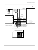

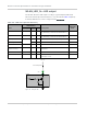

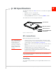
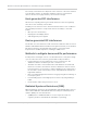
Table Of Contents
- Important Notice
- Safety and Hazards
- Limitation of Liability
- Patents
- Copyright
- Trademarks
- Contact Information
- Revision History
- 1: Introduction
- 2: Technology Overview
- 3: Standards Compliance
- 4: Electrical Specifications
- 5: RF Specifications
- 6: Power
- 7: Software Interface
- 8: Mechanical and Environmental Specifications
- 9: Regulatory and Industry Approvals
- A: Antenna Specification
- B: Design Checklist
- C: Testing
- D: Packaging
- E: References
- F: Acronyms
- Index

Product Technical Specification & Customer Design Guidelines
34 Proprietary and Confidential - Contents subject to change 2400074
WLAN_LED_N — LED output
The module drives the LED output according to [11] PCI Express Mini Card
Electromechanical Specification Revision 1.2, as described in Tab le 4-6 (below).
If desired, LED behavior can be configured using AT!LEDCTRL.
Figure 4-6: Example LED
Table 4-6: LED states (Default behavior)
State
LED behavior
Description
!LEDCTRL
index
Period (s) On Off
Off 0 0% 100% Module is not powered.
(W_DISABLE_N asserted with PCOFFEN=1)
N/A
Airplane mode 2 50% 50% Module is in low power mode.
(W_DISABLE_N asserted with PCOFFEN=0)
4
Power up 5.2 96% 4% Module is performing initial power up activities. N/A
Searching 96% 4% Module is searching service. 1
Connected 0.5 80% 20% Module has an active context. 3
Connected, with data
transfer occuring
0.5 80% 20% Module has an active context and data is being
transferred.
5
Error 1.6 20% 80% Device error has occurred. N/A
Attached 1 100% 0% Module has attached to a network and is not
currently in a call.
2
Current limiting Resistor
LED
VCC 3.3V
MIO
MiniCard