
User's Manual
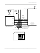


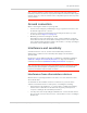
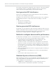
Table Of Contents
- Important Notice
- Safety and Hazards
- Limitation of Liability
- Patents
- Copyright
- Trademarks
- Contact Information
- Revision History
- 1: Introduction
- 2: Technology Overview
- 3: Standards Compliance
- 4: Electrical Specifications
- 5: RF Specifications
- 6: Power
- 7: Software Interface
- 8: Mechanical and Environmental Specifications
- 9: Regulatory and Industry Approvals
- A: Antenna Specification
- B: Design Checklist
- C: Testing
- D: Packaging
- E: References
- F: Acronyms
- Index

Electrical Specifications
Rev 4 Sep.11 Proprietary and Confidential - Contents subject to change 33
Control interface (Signals)
The MC7750 provides signals for:
• Power control of the module from the host
• LED driver output
These signals are summarized in Ta ble 4-5 and paragraphs that follow.
W_DISABLE_N — Wireless disable
The host device uses W_DISABLE_N (pin 20) to enable / disable the WWAN or
radio modem. When disabled, the modem cannot transmit or receive information.
Letting this signal float high allows the module to operate normally. This switch
follows the behavior described in
[11] PCI Express Mini Card Electromechanical
Specification Revision 1.2. This pin has a 20 k pull-up resistor. See Figure 4-5
on page 33 for a recommended implementation.
When integrating with your host device, keep the following in mind:
• The signal is an input to the module and should be driven LOW only for its
active state (controlling the power state); otherwise it should be floating or
(High impedance). It should never be driven to a logic high level. The module
has an internal pull-up resistor to Module Power (3.3V) in place, so if the
signal is floating or (high impedance), the module will power on.
• Wait for two seconds after asserting W_DISABLE_N before disconnecting
power.
• If the host never needs to assert this power state control to the module, leave
this signal unconnected from the host interface.
Figure 4-5: Recommended wireless disable connection
Table 4-5: Module control signals
Name Pin Description
Type
1
1. O — Digital pin Output; PU — Digital pin Input, internal pull up
W_DISABLE_N 20 Wireless disable (Main RF) PU
WLAN_LED_N 42 LED driver O
MiniCard
R
Wireless
disable control
1
2
3
Q
20k
Host
3.3V
PMIC for W_DISABLE_N